
ISOGROUND TWO
- Maximum strength with double columns
- Vertical and horizontal configuration
- ZM coated steel — 25-year design life
- Driving, concreting, anchoring — applicable to any terrain.
What is ISOGROUND TWO?
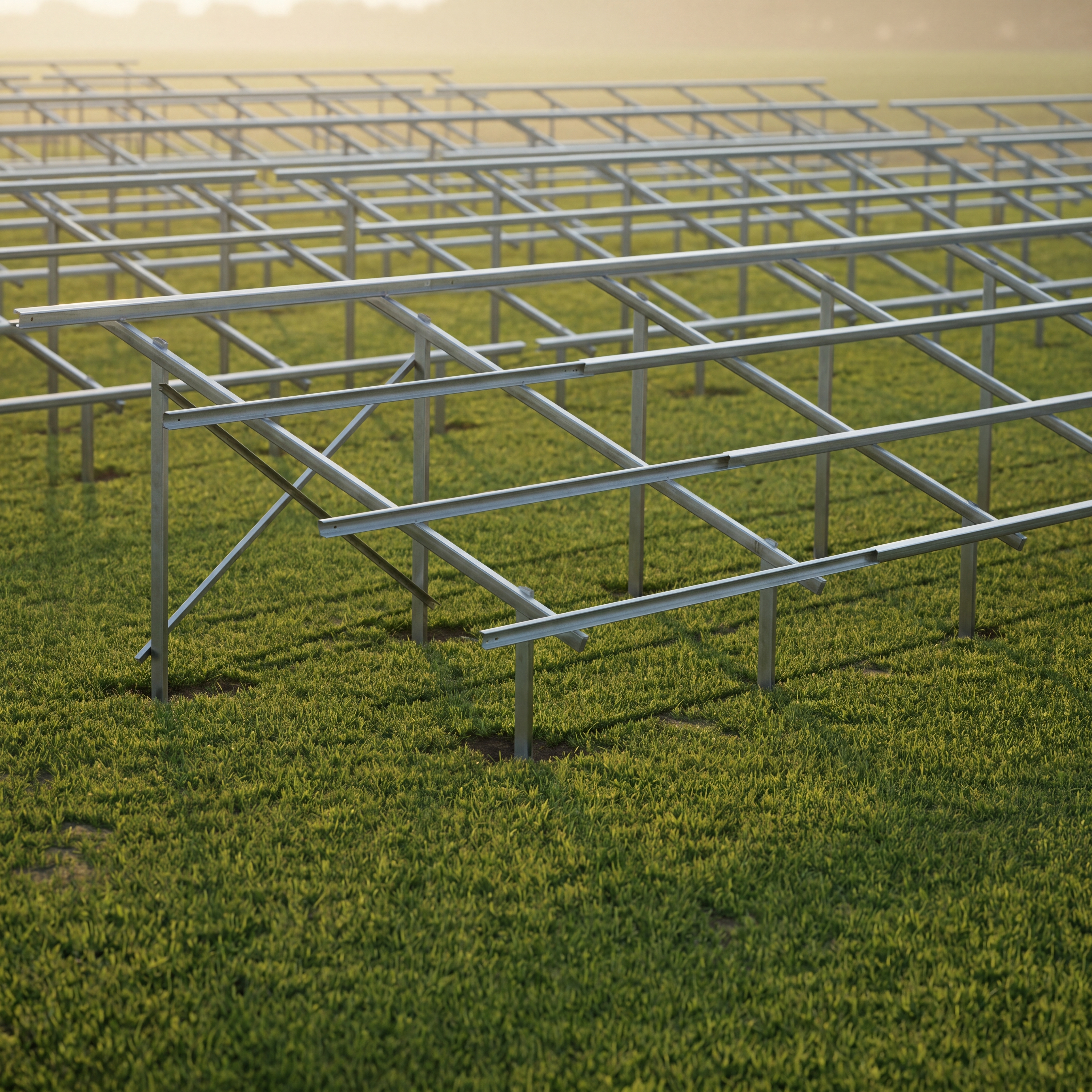
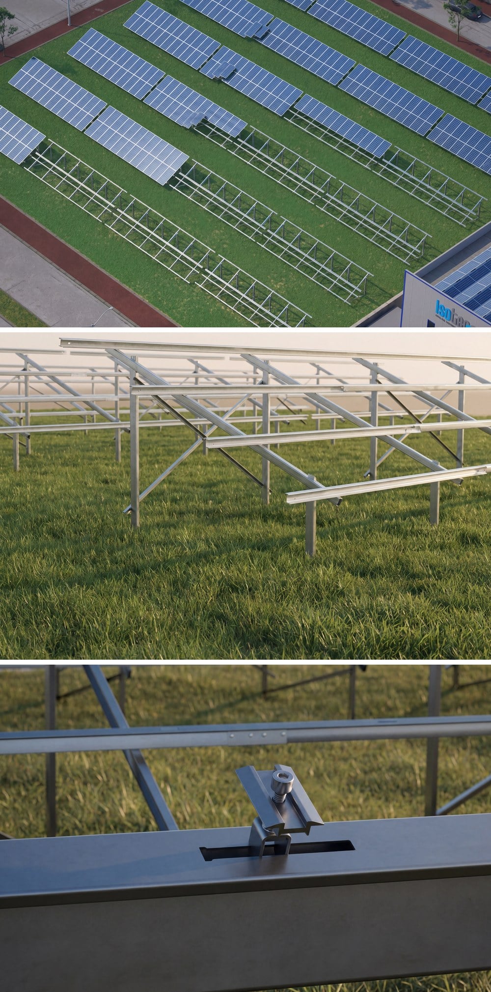
ISOGROUND TWO is the flagship variant of ISOTEC's family of fixed-tilt solar panel mounting systems for ground-mounted applications. Double vertical column thanks to its structure, it can withstand high wind and seismic loads. maximum strength It offers; thanks to its modular design From large-scale solar power plants of 50+ MW to agricultural irrigation applications. It is suitable for use in projects of all scales.
System; steel-steel (SS) and steel-aluminum (SA) It is offered in two main material variants. SS variant, This is the version where all load-bearing elements are manufactured from ZM-coated high-strength steel, and the platform lengths are custom-sized at the factory according to the project's static report. In project-based applications of 500 kWp and above It is the preferred main variant. SA variant This is the version where the purlins are made from Aluminum 6063-T66 alloy; aluminum purlins can be easily cut in the field. interconnector Thanks to its ability to be combined with other items, the length of the coffee table, which is not predetermined, can be adjusted accordingly. requiring supply from stock in applications — for example agricultural irrigation systems And in special project applications — it offers a practical solution.
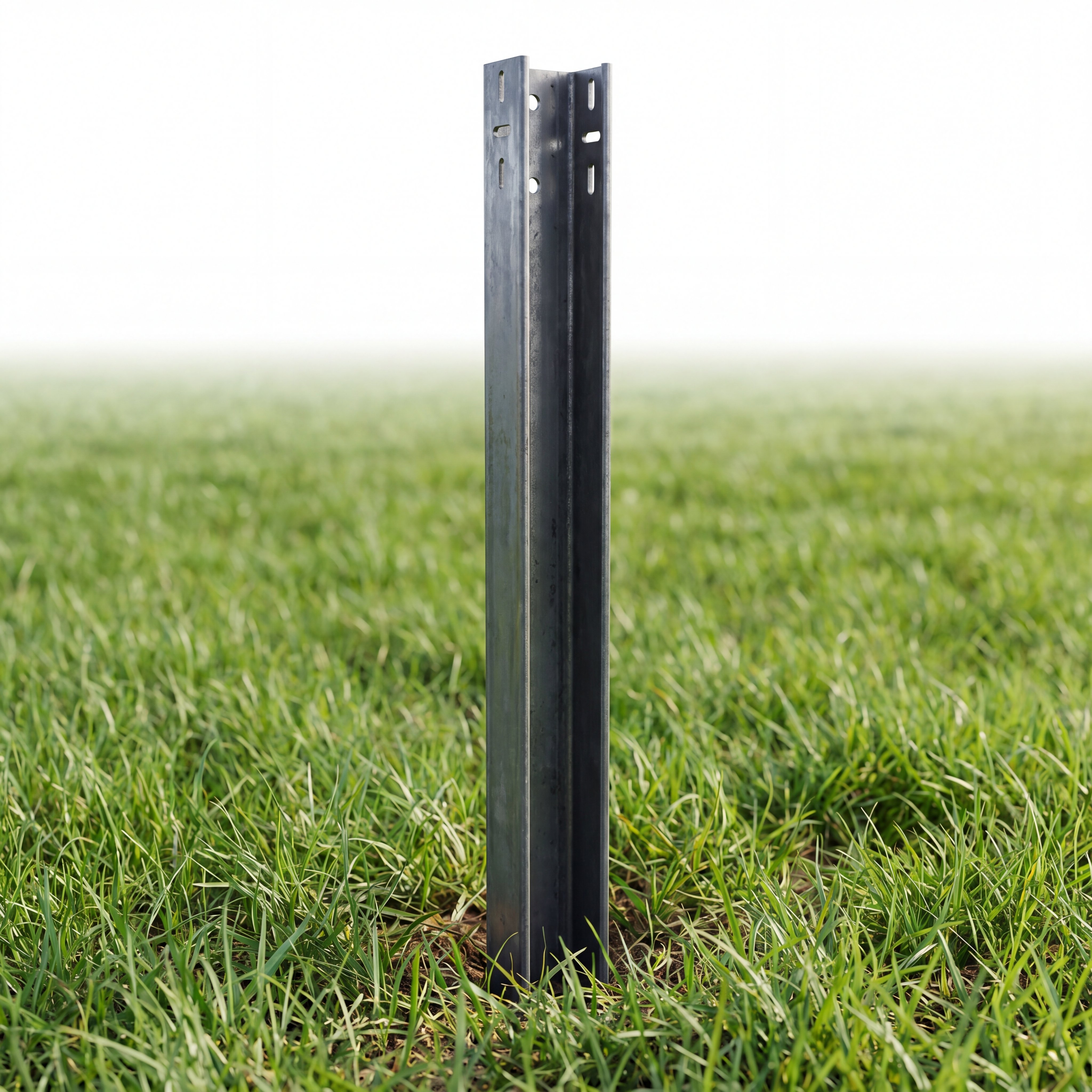
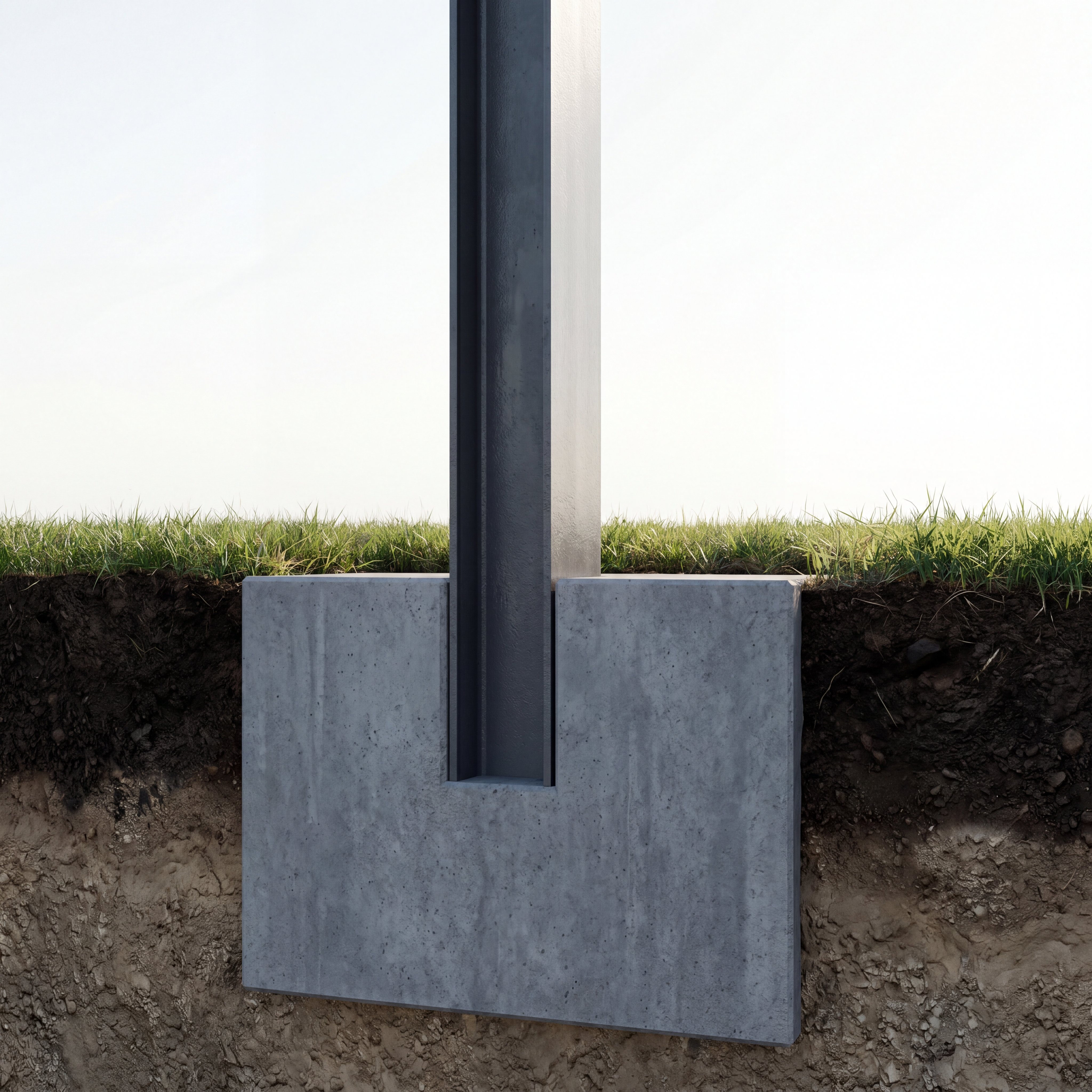
System; Ramming, concrete and anchor on concrete It can be adapted to every soil type with three different ground fixing methods. Standard on all load-bearing elements. EN 10346 compliant ZM coated high-strength steel (S350GD + ZM310) is used; this coating is classic HDG (hot-dip galvanized) compared to technology at the cutting edge self-healing behavior and 2x longer atmospheric resistance provides — for detailed information ZM Coating Technology You can browse our page. Aluminum purlins. 6063-T66, in fasteners stainless steel A2-70 It is used. Eurocode 0/1/3, TS 498 and TBDY 2018 It is designed with static calculations in accordance with standards.
ISOGROUND TWO — How it Works in the Field?
Click the icon on the video for full screen.
Product Family
Choose the profile height that best suits your project.
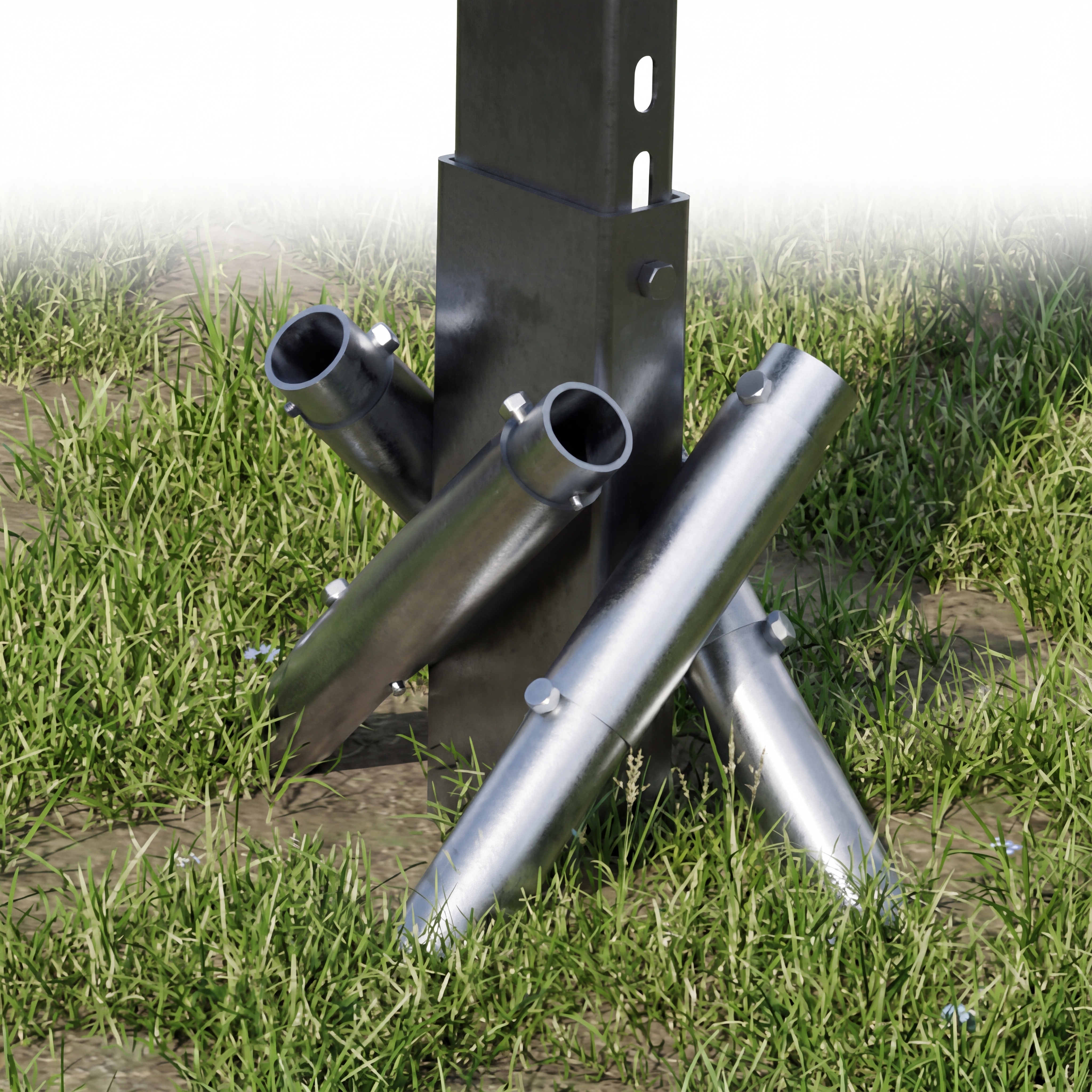
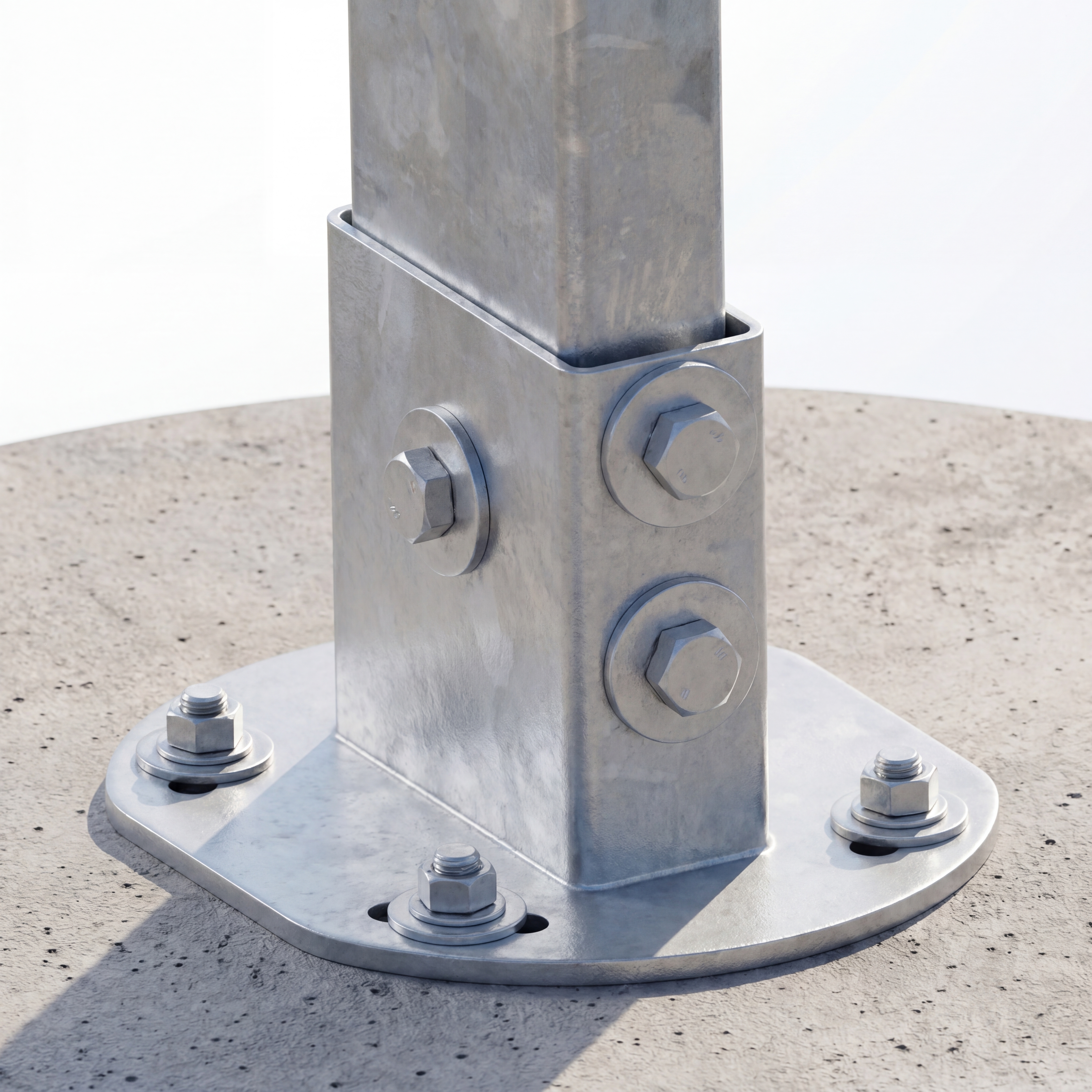
Ground Fixing Methods
4 different foundation fixing solutions suitable for all types of terrain.
Technical Data
| Area of Use | Ground / Land |
| System Type | Fixed-tilt, double-column |
| Material Variants | SS (Steel-Steel) / SA (Steel-Aluminum) |
| Panel Placement | 2 Vertical, 3 Vertical, 4 Horizontal, 5 Horizontal |
| Panel Size (L) | 1,500 – 2,500 mm |
| Panel Size (W) | 990 – 1,330 mm |
| Panel Thickness (H) | 30 – 45 mm |
| Panel Weight | 15 – 25 kg |
| Panel Angle | 10° – 30° |
| Ground Fixing | Driving / Concrete Pouring / Anchoring on Top of Concrete |
| Column / Beam / Cross | ZM coated steel (S350GD/S450GD + ZM310) |
| Purlin (SS) | ZM coated steel Z-profile, 1.5 mm |
| Purlin (SA) | Aluminum 6063-T66, 1.3 mm |
| Panel Holder / Clamp | Aluminum 6063-T66 / EN 6005 |
| Fasteners | Stainless steel A2-70 (according to DIN standards) |
| Design Standards | Eurocode 0/1/3, TS 498, TBDY 2018 |
| Design Life | 25 years (C3/C4 corrosion class) |
System Components
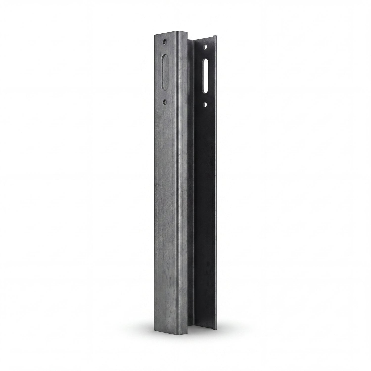
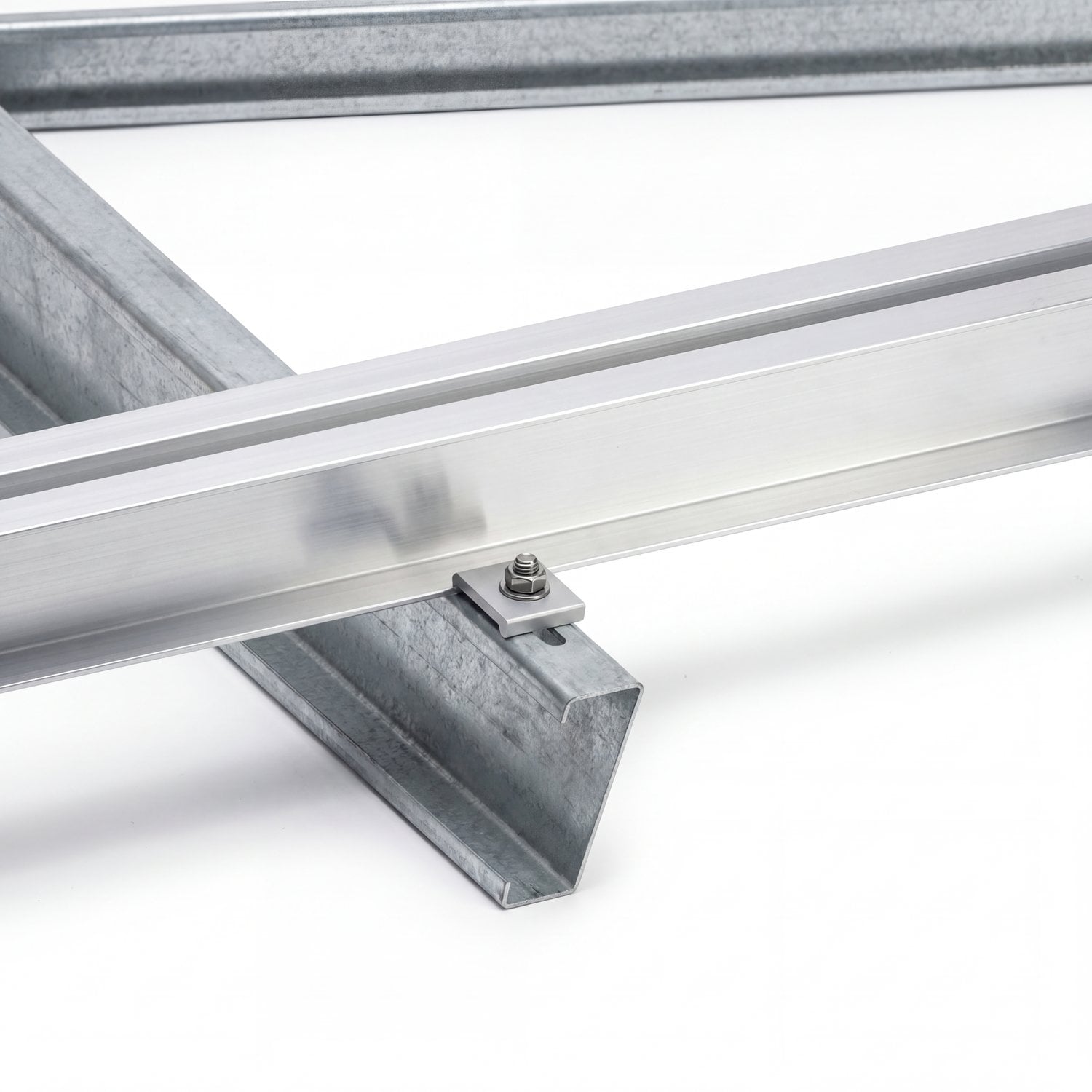
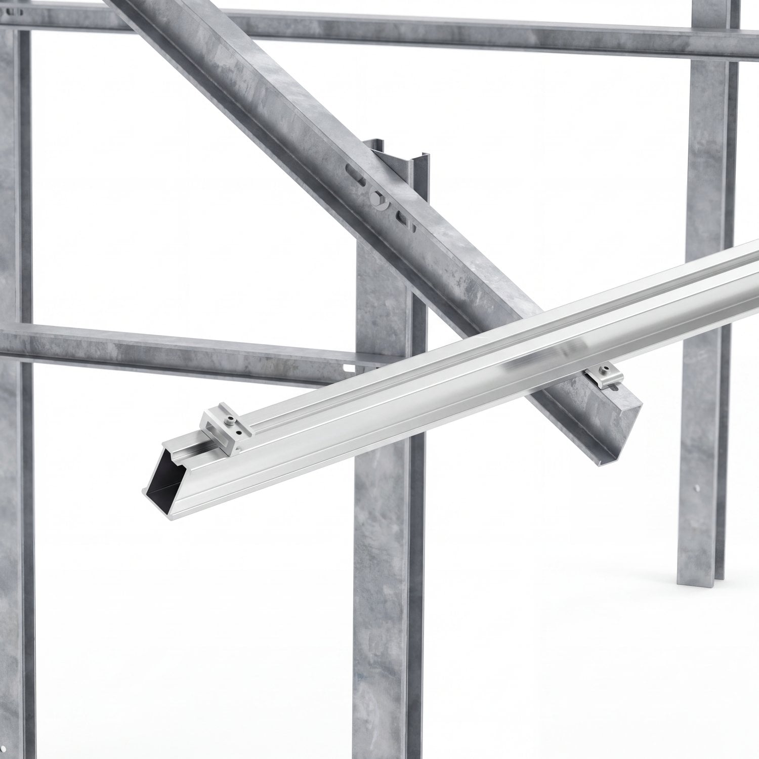
ZM coated high-strength steel C-profile, rammed-pile type. Short vertical posts supporting the front of the panel are driven directly into the ground.
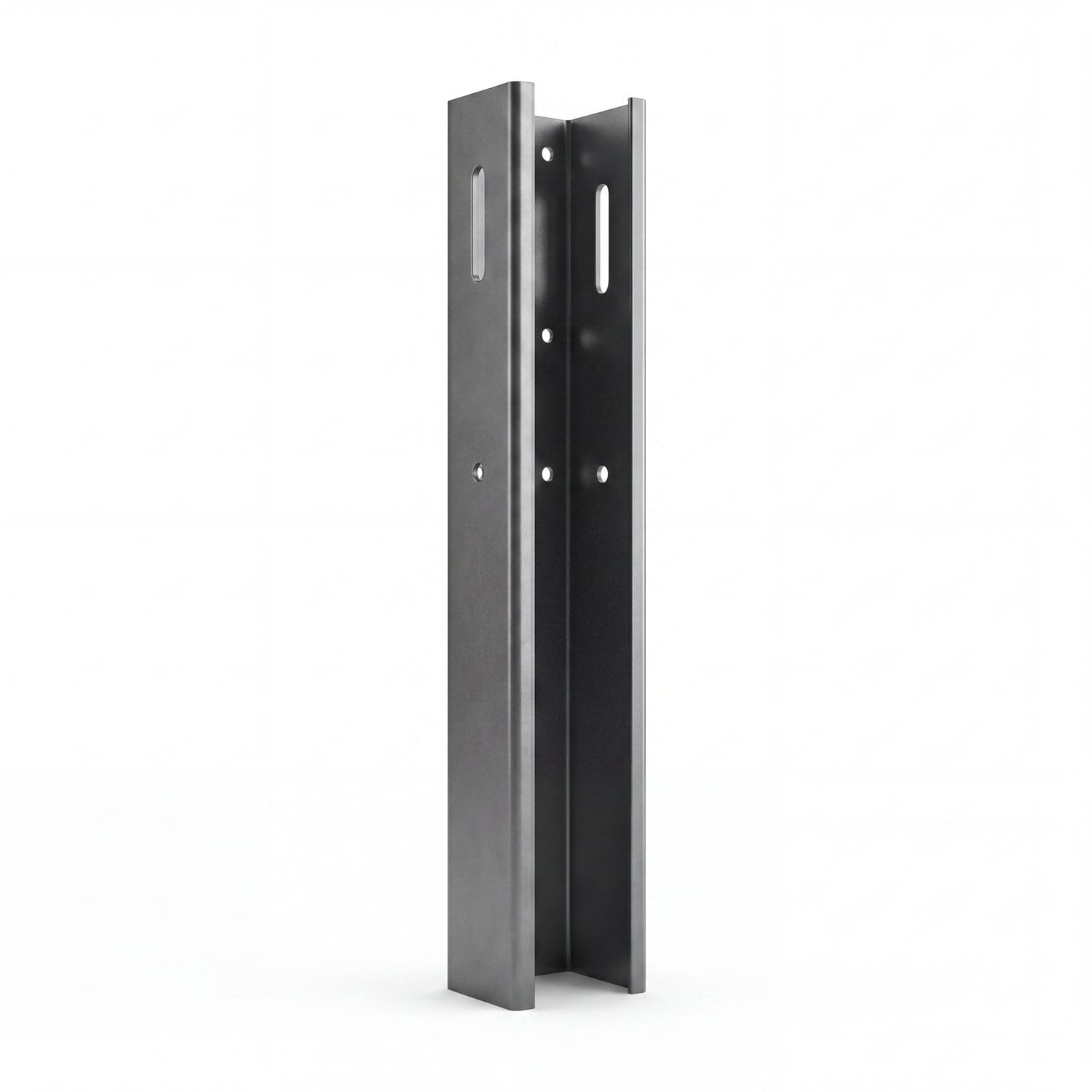
ZM coated high-strength steel C-profile, bolted type. Longer than the front column to form the panel angle; bolted directly into the ground.
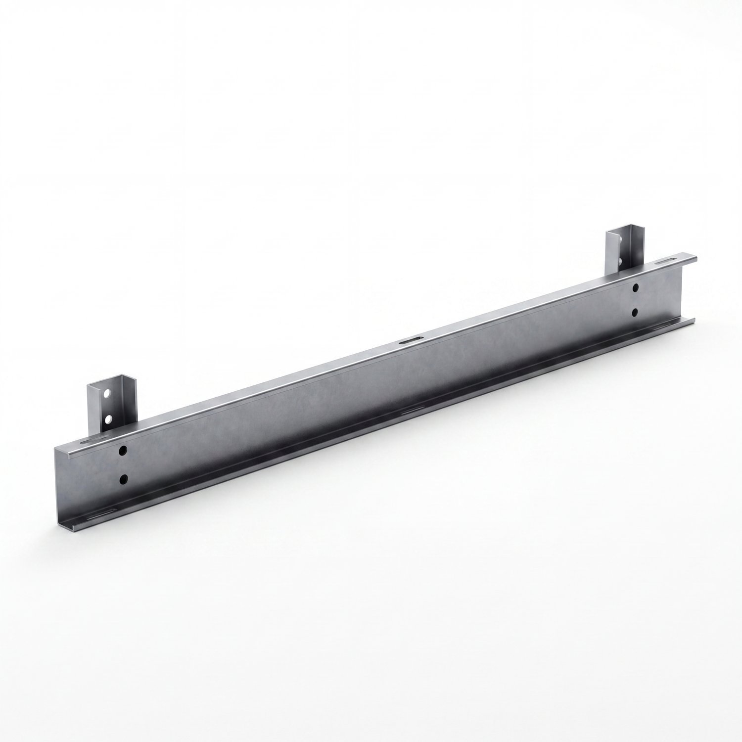
C-profile, 2 mm, ZM coated steel. Main load-bearing element connecting the front and rear columns horizontally.
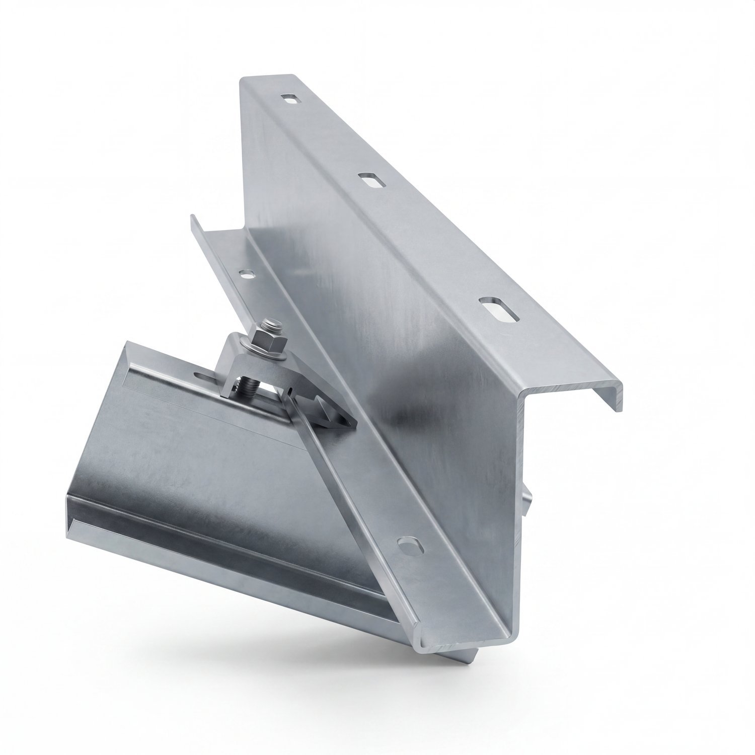
Z-profile 1.5 mm, ZM coated steel. Horizontal support on which the panels rest; used in the SS variant.
The SA variant features a center clamp set that secures panel modules to an aluminum Z-pillar. The top-clamping design allows it to be placed between two panels, gripping both simultaneously.
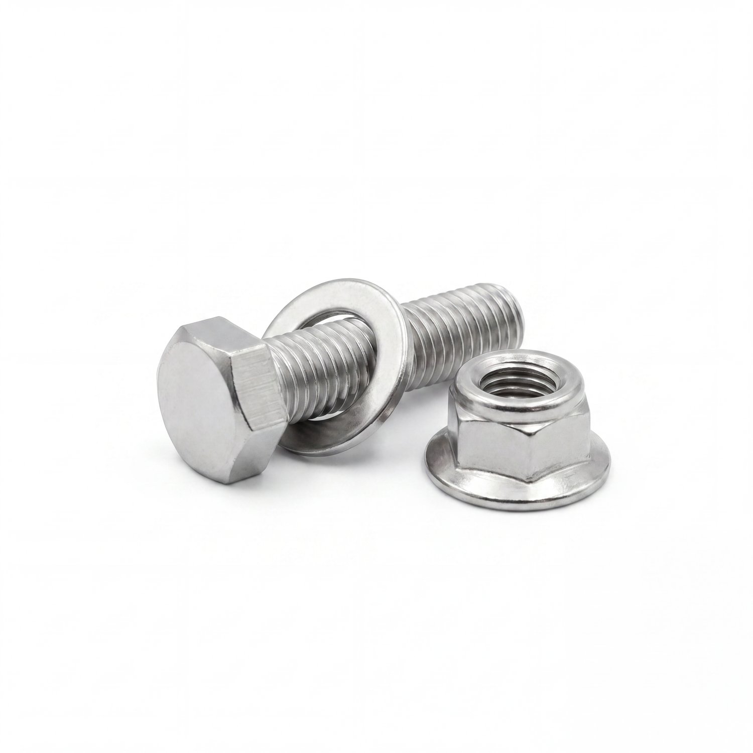
Stainless steel A2-70 bolt/nut/washer set (conforms to DIN 912, DIN 933, DIN 9021, DIN 6923 standards). Used at all system connection points.
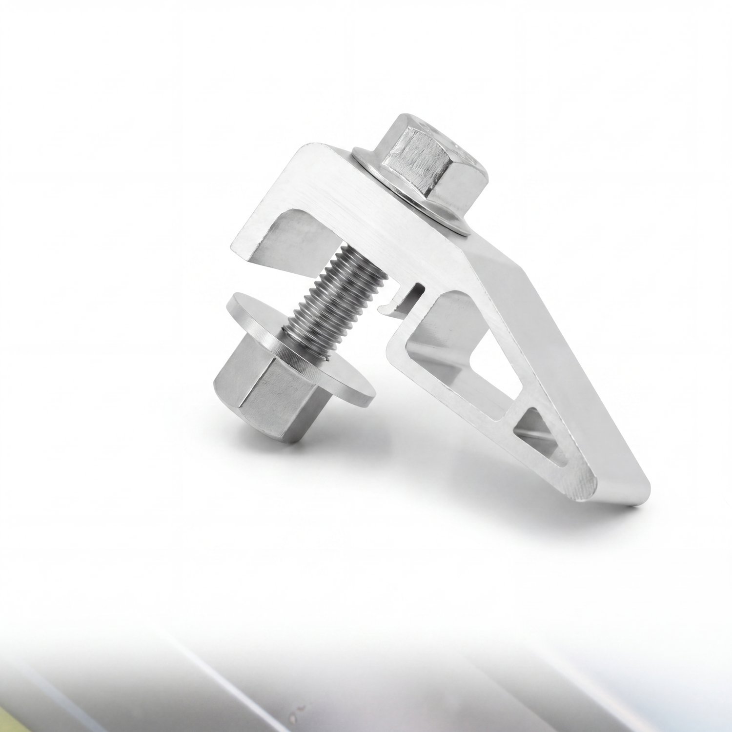
SA variant-specific adapter; attaches aluminum Z-beam to steel beam by clamping it. It slides into the beam slot via a central bolt from above.
In the SA variant, the SET clamp mounting point is where the panel modules are fixed onto the aluminum Z-purlin. It is attached to the top flange of the purlin with a hex bolt.
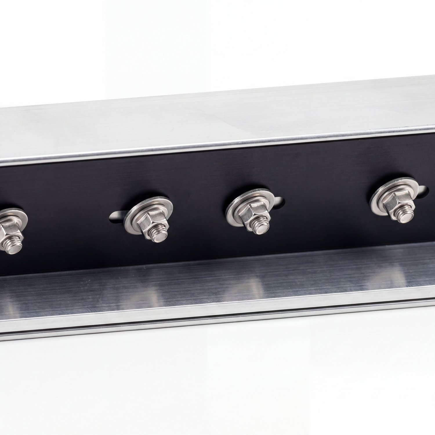
A splice plate system that connects the ends of two Z-shaped purlins from the outside. Provides a high-strength connection with 4 stainless steel hex bolts + top and bottom plates.
Options & Accessories
Additional solutions offered for optimization specific to your project.
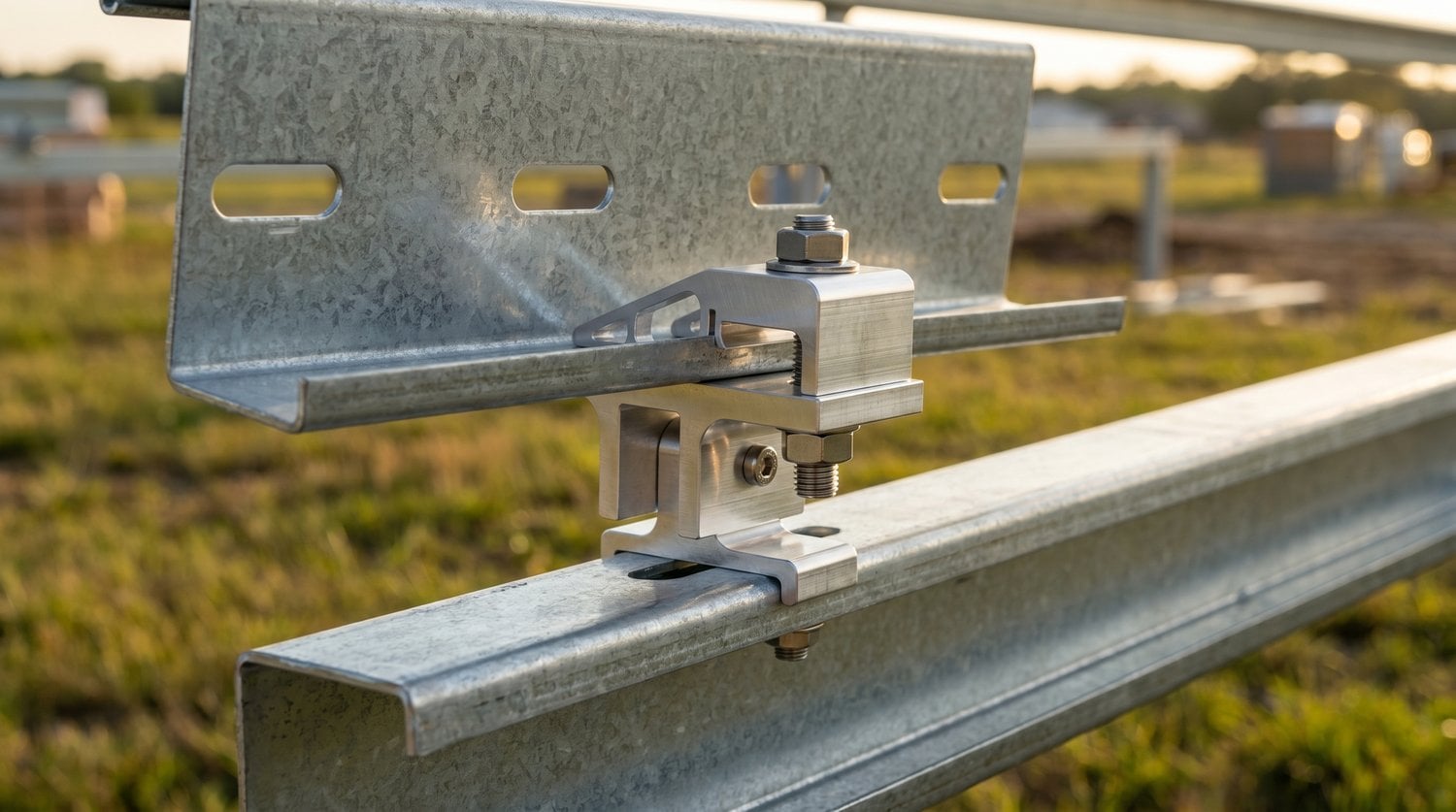
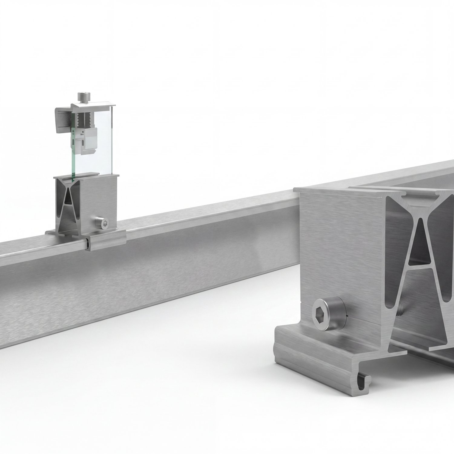
Parts Added Based on Static Calculation Results
These components are not selected as optional parts for the project; they are chosen by the ISOTEC engineering team. static calculation report As a result, it is automatically included in the system if necessary.
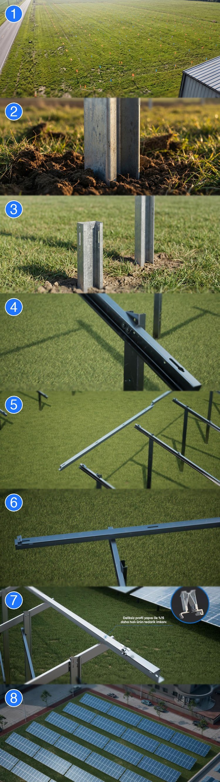
Easy Assembly
-
1Site Preparation & Marking According to the soil investigation report, column locations, panel spans, and slope applications are determined. Drainage and access routes are also identified.
-
2Basic Application For driving, columns are erected to a depth of 1–2 m; for concreting, the process includes foundation formwork + pouring + drying; and for anchoring, torqued anchors are placed on ready-mixed concrete/rock.
-
3Column Assembly Front and rear columns are erected; they are fixed to the foundation with DIN 912 M8 bolts. Horizontal and vertical checks are performed using a spirit level.
-
4Main Beam Assembly The main beam connecting the two columns is installed. DIN 933 M10/M12 bolts; torque: 48–50 N·m for M10, 80–90 N·m for M12.
-
5Cross-Support (Optional) In seismic zones, DB (East-West) cross bracing is used, and in high wind zones, KG (North-South) cross bracing is used. This is implemented according to the static report.
-
6Aşık Assembly & IsoClamp Connection Z-profile purlins (SS: ZM coated steel — SA: 6063-T66 aluminum) are placed at a right angle to the main beam and IsoClamp It is fixed to the beam with a clamp. A single central bolt (M10×45 or M12×45) passes through the slot hole in the aşık, and the clamp grips the beam flange from below. No holes are drilled in the beam.. Since the need to align the holes of the two parts is eliminated, East-West bevel and assembly tolerances are corrected in the field along the slot. Torque: 48–50 N·m for M10 (8.8·zinc). Aşıklar is joined end-to-end with L310N (SS) or aluminum connector (SA).
-
7Handcuff Placement A center clamp is placed between the panels, and edge clamps are placed at the panel ends. SS: single clamp — SA: SET clamp system.
-
8Panel Assembly The panels are mounted on the purlins; they are secured with center and edge clamps (SS: single clamp, SA: SET system). Torque: 17 N·m.
Site Preparation & Soil Investigation
In ground-mounted solar energy systems, correctly selecting the column size and foundation fixing method is crucial for the system's success. 25-year design life ISOTEC ensures reliable operation throughout every field project. soil survey report It is recommended to start with this; static calculation reports are based on this report.
Regular Maintenance = 25 Years of Investment Guarantee
The ISOGROUND TWO system, thanks to its ZM-coated high-strength steel body and stainless A2-70 fasteners... minimum maintenance It is designed to provide reliable service for many years. However, periodic checks, the system 25-year design life structural strength, occupational safety and throughout warranty terms It is critically important for its protection.
The following periodic checks are carried out:, system owner or implementer/EPC company It should be performed regularly.
⚠ Warranty Terms: In order for the warranty period to remain valid, the annual maintenance inspection reports are required. info@isotec.com.tr It must be sent via email to [email address].
| Maintenance Type | Frequency | Explanation |
|---|---|---|
| Visual Inspection | Once a year | Signs of corrosion, loose joints, physical damage — quick overview |
| Connection Torque Control | After the first 6 months, then once a year. | The first torque test should be performed 6 months after initial installation, followed by annual tests. Torque values vary depending on the connection type: Column-beam (M12): 80–90 N·m • Beam–aşık / IsoClamp (M10 · 8.8): 48–50 N·m, (M10 · A2-70): 38–42 N·m, (M12 · 8.8): 45–50 N·m • Panel clamp: 14–18 N·m |
| Panel Surface Cleaning | Twice a year | Dust, bird droppings, pollen — to prevent yield loss. |
| Cross Support & Clamp Control | Once every 2 years | Especially after seismic activity or strong winds. |
| Drainage & Site Control | Once a year | Post-rainfall site drainage, control of water pooling at the base of columns, or soil erosion. |
| Planting & Shade Control | Twice a year | Cleaning weeds/branches/wild plants that create shade between and in front of panels — for yield and fire safety. |
Situations Requiring Early Intervention
Regulations & Standards
The ISOGROUND TWO system design conforms to the following international and national standards.
- Eurocode 0 — Fundamentals of Structural Design
- Eurocode 1-3 — Snow Loads
- Eurocode 1-4 — Wind Loads
- Eurocode 3-1-1 — Design of Steel Structures
- Eurocode 3-1-8 — Steel Joints
- Eurocode 9 — Design of Aluminum Structures
- TS 498 — Calculation Values of Loads to be Taken into Account in the Sizing of Structural Elements
- TBDY 2018 — Turkish Building Earthquake Regulations
- TS EN 1990 / 1991-1-3 / 1991-1-4 / 1993 — Building design standards
- TS EN 10025 — Structural steel grades (S350GD, S450GD)
- TS EN 10346 — Continuous hot-dip coated steel strips (ZM coating)
- EN 10346 — ZM (Zn-Al-Mg) coating standard (ZM310, ZM430)
- ISO 12944-2 — Protection with paints and varnishes — Environmental classification (C3/C4)
- ISO 14713-1 — Corrosion protection in steel structures — Galvanizing guide
- DIN 55634-1 — Coated steel corrosion test
- Magnelis® / PosMAC® — Manufacturer technology documents (ZM Coating Technology page)
- SCI P358 — Simple Joints to Eurocode 3
- SCI P398 — Moment-Resisting Joints to Eurocode 3
- SCI P394 — Wind Actions to Eurocode 1
- DIN 912 / 933 / 9021 / 6923 — Standards for bolts, nuts, and washers
- DIN 7504K — Smart screw (in SA variant)
- EN ISO 3506 — A2-70 stainless steel fastener
- UL 2703 — Certification of solar panel mounting systems
- IEC 61730 — Panel safety standard
- IEC 61400 — Wind loads (PV applications)
- Before the package is opened — Protect the products from moisture and rain; prevent the products inside the pallet from coming into contact with water.
- When the packaging is opened — Seal box openings with tape; keep small boxes of fasteners closed, and repackage bagged products.
- Throughout storage — Do not leave pallets and boxes on wet surfaces; protect the products from dust and dirt.
- Risk of moisture damage — Moisture trapped in the packaging can cause "white rust" on galvanized steel, discoloration on aluminum, and surface corrosion on Magnelis® coating.
- Stacking arrangement — Do not stack materials that have not been stacked by ISOTEC. If moisture is noticed, move the product to a separate, dry area and report it to ISOTEC.
- Full instructions (PDF): Turkish · German · English
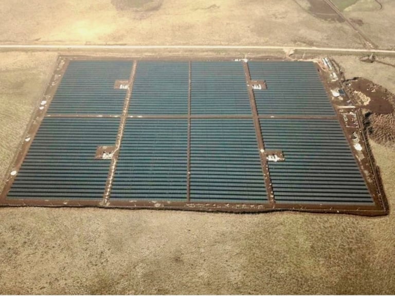
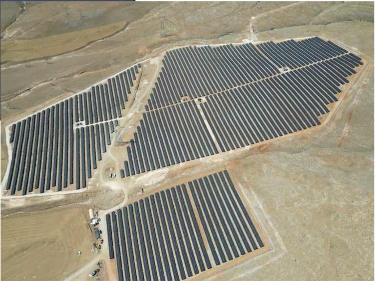
Relevant Reference Projects
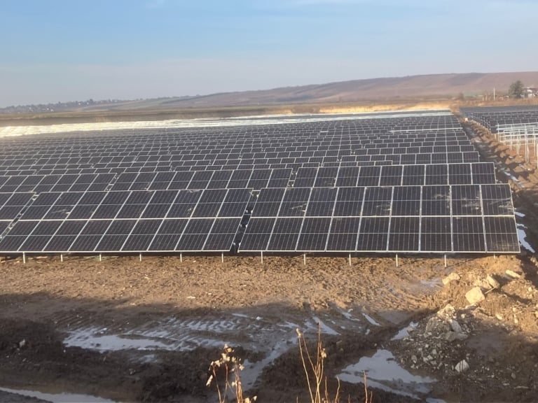
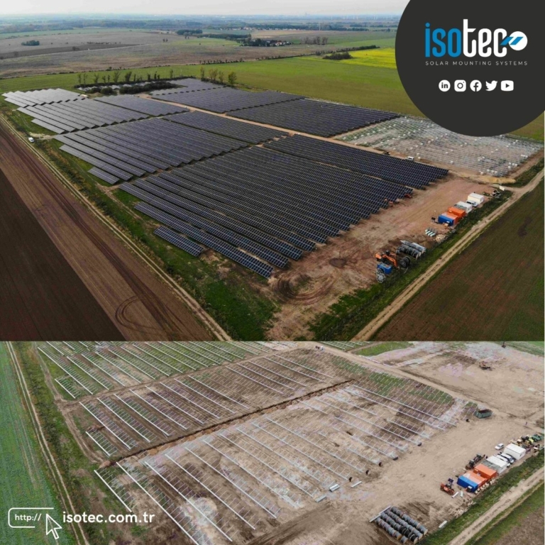
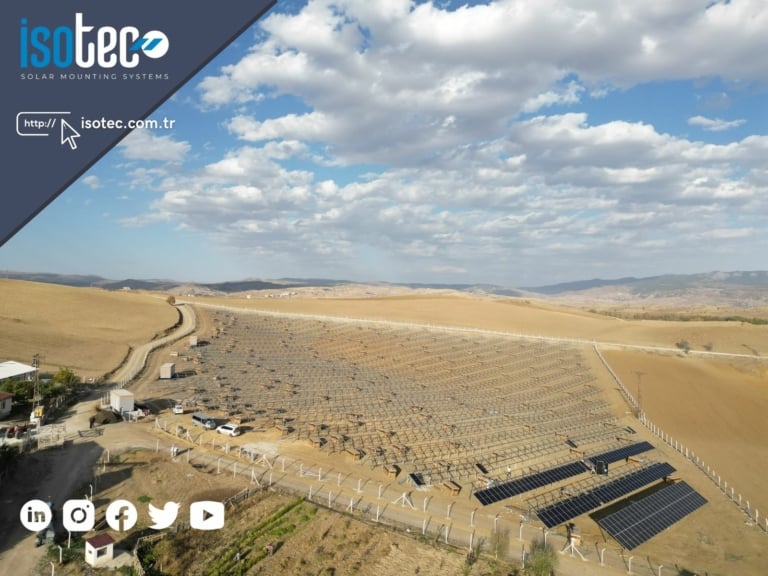
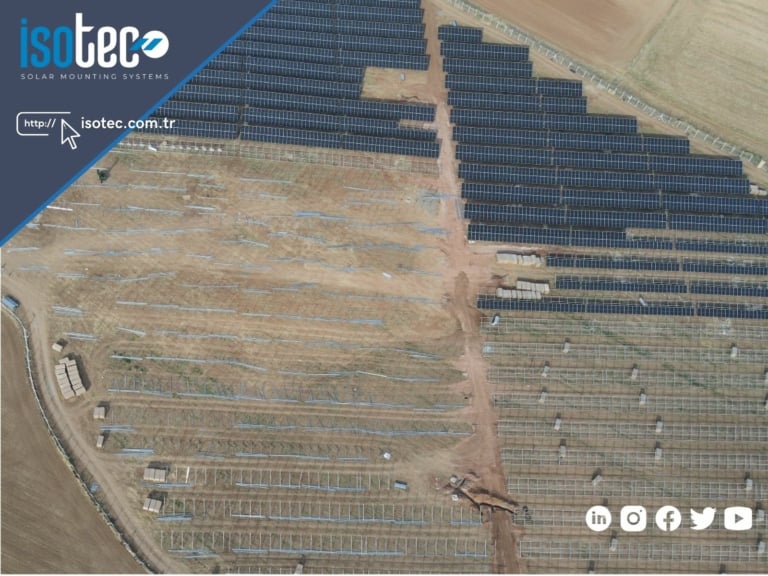
Our outstanding ground-mounted solar power projects implemented with ISOGROUND TWO.
Technical Documents
Download all technical documentation for the product.
Let's work together to determine the most suitable ISOGROUND TWO configuration for your project.
BF Device · Bifacial Shading Advantage
There are two different approaches in the industry. Why is ISOTEC's BF apparatus both economical and high-performing?
Why is shading important in bifacial panels?
Bifacial (double-sided) solar panels generate electricity from both their front and back surfaces. The back surface captures radiation reflected from the ground and coming from the side edges — typically. %15-20 ek üretim provides.
The critical point: Any part (purlin, beam, cable) that blocks light falling on the back surface of the panel → on the back surface shadow lines It creates a shadow, and the cells under this shadow lose productivity. Between the purlin and the panel... distance and the purlin cross-sectional area These are the determining parameters.
Therefore, to get the most out of a bifacial investment, the design of the mounting system is critical.
Two Design Philosophies in the Industry
There are two main approaches in the industry to reduce bifacial shadowing:
Inclined C-Beam competitors
The beam runs parallel to the panel at the same angle. A single long C-profile provides grip along the panel.
- ✓ Minimal shade, high bifacial yield.
- ✗ Long steel beams, high material costs.
- ✗ In sloping structures, column heights vary.
- ✗ Tolerances are tight, assembly takes a long time.
Vertical Beam + Horizontal Z-Purlin ISOTEC + BF
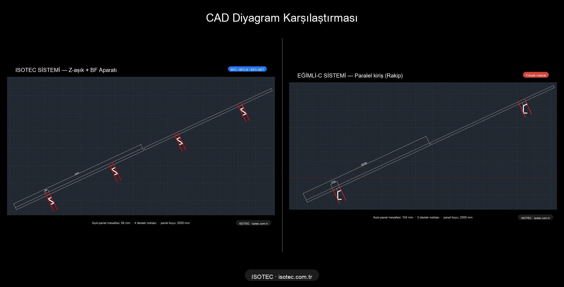
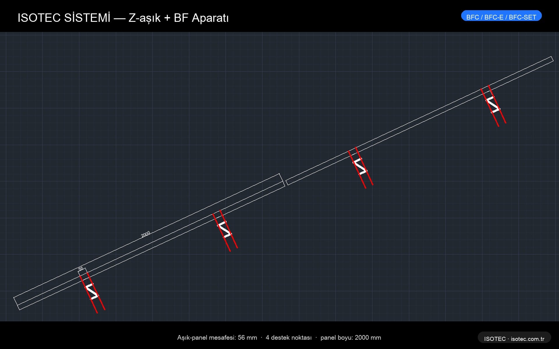
The beams are vertical (perpendicular to the ground, short). The Z-profile purlins extend horizontally. A BF 56 mm spacer is inserted between the purlin and the panel.
- ✓ Low steel content, quick assembly, economical.
- ✓ Bifacial performance with BF apparatus and Inclined-C equal
- ✓ Standard column, easy supply.
- ✓ Slot design compatible with thermal expansion.
CAD comparison — purlin-panel distances
How does the BF adapter work?
The ISOTEC BF adapter is a device placed between the Z-shaped purlin and the bottom surface of the panel. spacer + clamp systemIt maximizes the radiation falling on the back surface of the panel by creating a distance of 56 mm.
Design features
- Spacer body: EN AW-6005A T6 anodized aluminum (3.0 mm wall)
- Distance: The distance between the purlin's top surface and the panel's bottom surface is 56 mm.
- Slot design: Panel thermal expansion accommodated (±2 mm tolerance)
- Screw: Stainless steel A2 M8×40 hexagonal
Clamp variations
| Code | Medicine | Use |
|---|---|---|
| BFC | Glass-to-glass edge | For frameless glass-to-glass panels at panel edges. |
| BFC-E | Medium grip | Center panel, shared grip, frameless. |
| BFC-SET | Complete set | All components are pre-packaged, quick assembly. |
CAD details — ISOTEC system
Bifacial Radiance Simulation Results
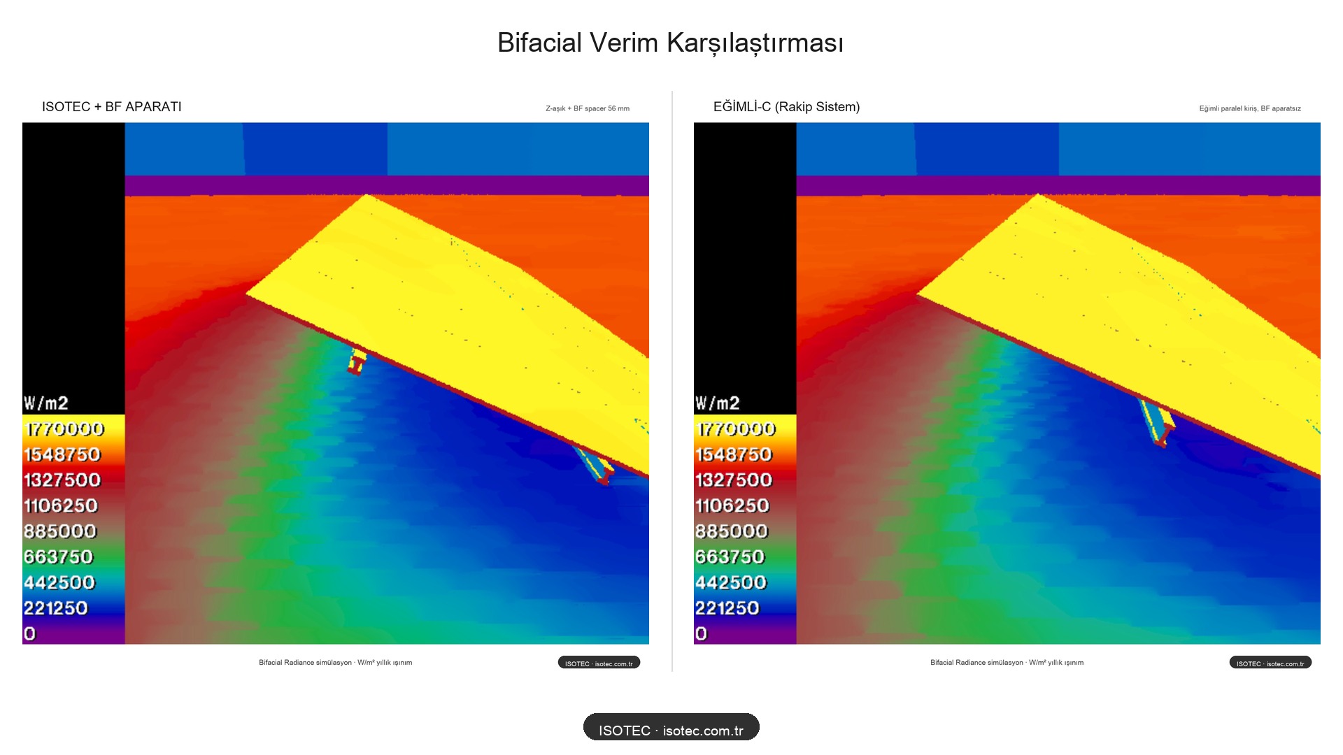
The results are from NREL's (US National Renewable Energy Laboratory) open-source program. Bifacial Radiance This was achieved using a Python library. A scanner-based radiation calculation is performed that accurately reflects field conditions.
Heat map comparison
Warm (yellow) colors indicate high irradiation (1.77 MWh/m² annually), while cool (blue) colors indicate shaded areas. In both systems, the front surface of the panel (the upper yellow area) receives homogeneous irradiation; the difference is the panel. on the back surface It is seen.
Numerical results
| System | Bifacial Gain | Shadow Line | Cost |
|---|---|---|---|
| Sloping-C (Opponent) | ~%18-20 | 1 big | 💰💰💰 High |
| ISOTEC + BF Adapter | %18 | 2 small | 💰 Economical |
| ISOTEC (without BF adapter) | ~%10-12 | 2 nearby shadows | 💰 Lowest |
The same bifacial production, shorter beam, less steel, faster assembly. The cost difference is significant at the field scale.