
ISOGROUND ONE
- Single-column fixed-tilt system
- Preferred on hard ground to reduce the number of columns
- Portrait and landscape layout
- Steel/Steel and Steel/Aluminum options
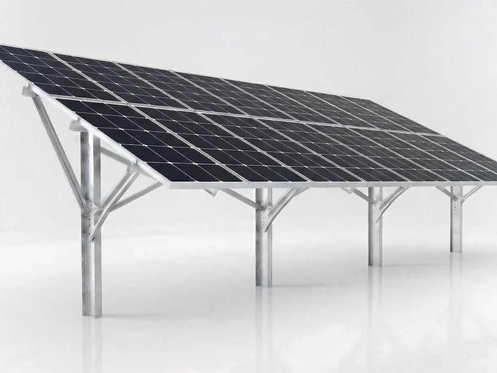
What Is ISOGROUND ONE?
ISOGROUND ONE is the single-column solution in ISOTEC's family of fixed-tilt ground-mount solar mounting systems. It is preferred on hard and rocky ground to reduce the number of columns.
The system suits portrait and landscape module layouts and is installed at a module tilt of 10° – 35° (fixed tilt). Steel–steel (SS) and steel-aluminum (SA) options are available; all fasteners are made of A2-70 stainless steel.
ISOGROUND ONE has been used in 180 MW of installations. Contact the ISOTEC engineering team to determine the right configuration based on soil hardness, site slope, module size and structural requirements.
Ground Fixing Methods
Fixing solutions determined by the soil survey
Technical Data
| Area of Use | Ground / Open Field |
| System Type | Fixed-tilt, single-column |
| Material Variants | SS (Steel-Steel) / SA (Steel-Aluminum) |
| Panel Placement | Portrait and landscape |
| Panel Size (L) | 1,500 – 2,500 mm |
| Panel Size (W) | 990 – 1,330 mm |
| Panel Thickness (H) | 30 – 45 mm |
| Panel Angle | 10° – 35° |
| Ground Fixing | Driving, core drilling or anchoring on concrete, depending on the soil survey |
| Material | Steel support structure; aluminum 6063-T66 rails and clamps; A2-70 stainless steel fasteners |
| Installed capacity | 180 MW |
System Components
Easy Assembly
Technical Documents
Download all technical documentation for the product.
Let us determine the best ISOGROUND ONE configuration for your project together
BF Attachment · Bifacial Shading Advantage
There are 2 different approaches in the industry. Why is ISOTEC's BF attachment both economical and high-performing?
Why is shading important in bifacial panels?
Bifacial (double-sided) solar panels generate electricity from both their front and back surfaces. The back surface captures radiation reflected from the ground and coming from the side edges — typically %15-20 ek üretim provides.
The critical point: Any part (purlin, beam, cable) that blocks light falling on the back surface of the panel → on the back surface shadow lines creates, and the cells under the shadow lose output. The purlin-to-panel distance and the purlin's cross-sectional area are the determining parameters.
Therefore, to get the most out of a bifacial investment, the design of the mounting system is critical.
Two Design Philosophies in the Industry
There are two main approaches in the industry to reduce bifacial shadowing:
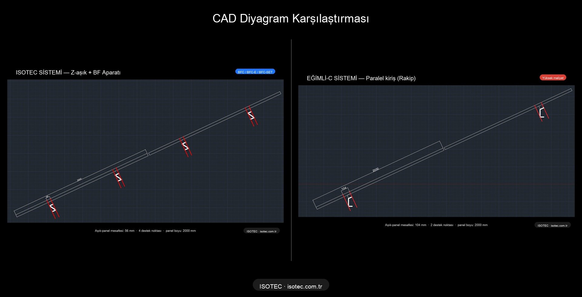
Inclined C-Beam Competitors
The beam runs parallel to the panel at the same angle. A single long C-profile provides grip along the panel.
- ✓ Minimal shade, high bifacial yield.
- ✗ Long steel beams, high material costs.
- ✗ In sloping structures, column heights vary.
- ✗ Tolerances are difficult, installation takes a long time
Vertical Beam + Horizontal Z-Purlin ISOTEC + BF
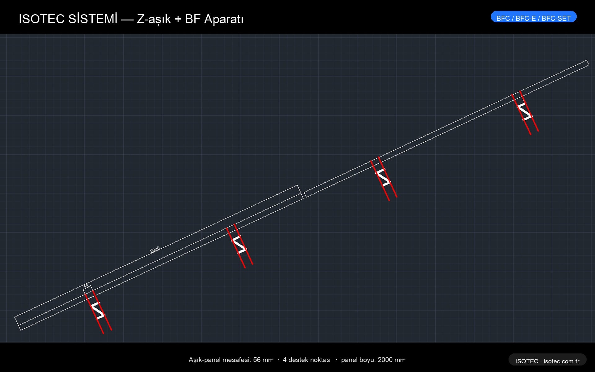
The beams are vertical (perpendicular to the ground, short). The Z-profile purlins extend horizontally. A BF 56 mm spacer is inserted between the purlin and the panel.
- ✓ Low steel content, quick assembly, economical.
- ✓ Bifacial yield with BF adapter vs. Inclined-C equal
- ✓ Standard column, easy supply.
- ✓ Slot design compatible with thermal expansion.
CAD comparison — purlin-panel distances
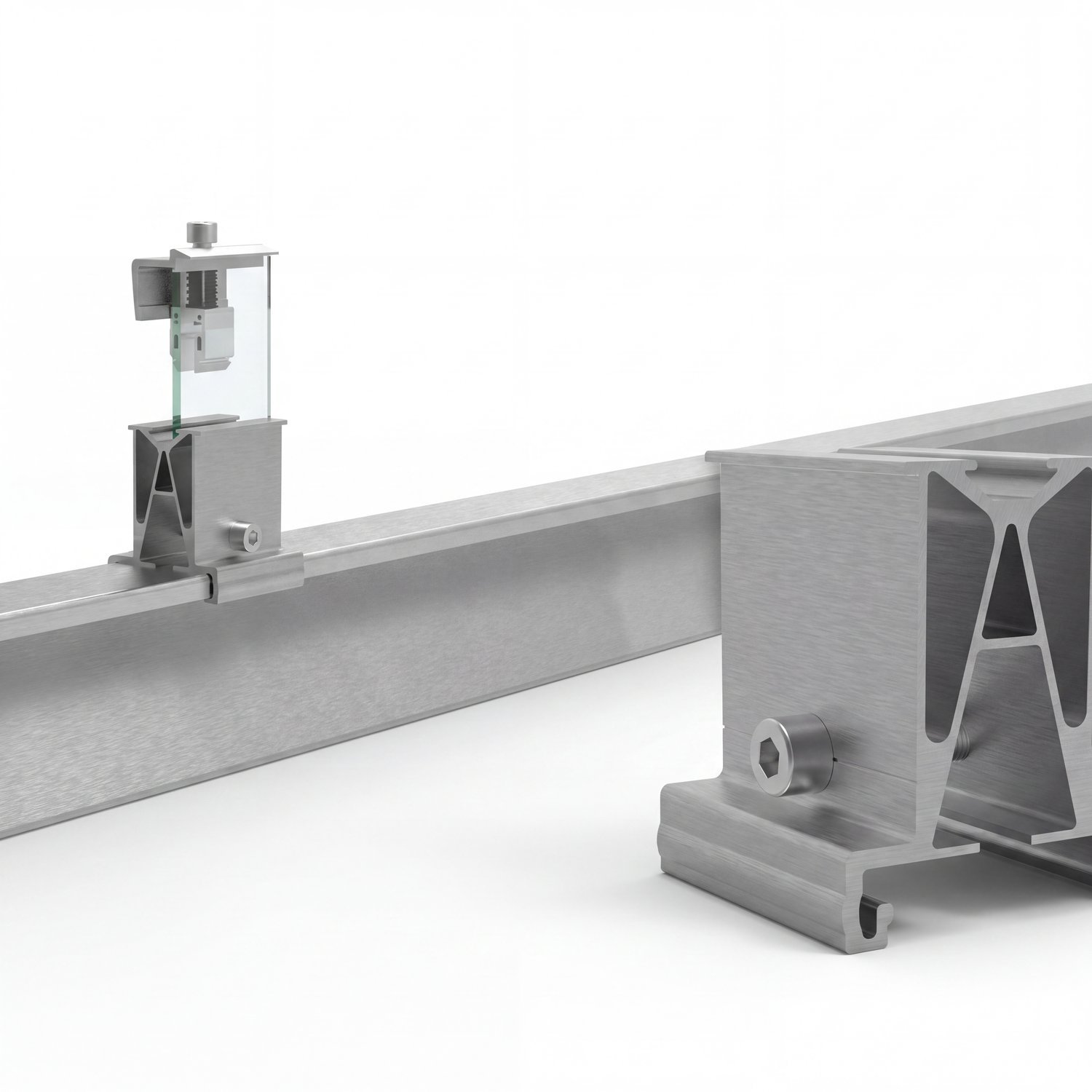
How does the BF adapter work?
The ISOTEC BF adapter is placed between the Z-purlin and the underside of the panel as a spacer + clamp system. By creating a 56 mm gap, it maximizes the irradiance reaching the back surface of the panel.
Design features
- Spacer body: EN AW-6005A T6 anodized aluminum (3.0 mm wall)
- Distance: The distance between the purlin's top surface and the panel's bottom surface is 56 mm.
- Slot design: Panel thermal expansion accommodated (±2 mm tolerance)
- Screw: Stainless steel A2 M8×40 hexagonal
Clamp variations
| Code | Type | Usage |
|---|---|---|
| BFC | Glass-to-glass edge | For frameless glass-to-glass panels at panel edges. |
| BFC-E | Center grip | Center panel, shared grip, frameless. |
| BFC-SET | Complete set | All components are pre-packaged, quick assembly. |
CAD details — ISOTEC system
Bifacial Radiance Simulation Results
Results were obtained using NREL's (US National Renewable Energy Laboratory) open-source Bifacial Radiance Python library. A scan-based irradiance calculation that accurately reflects field conditions is performed.
Heat map comparison
Warm (yellow) colors indicate high irradiation (1.77 MWh/m² annually), while cool (blue) colors indicate shaded areas. In both systems, the front surface of the panel (the upper yellow area) receives homogeneous irradiation; the difference appears on the panel's rear surface .
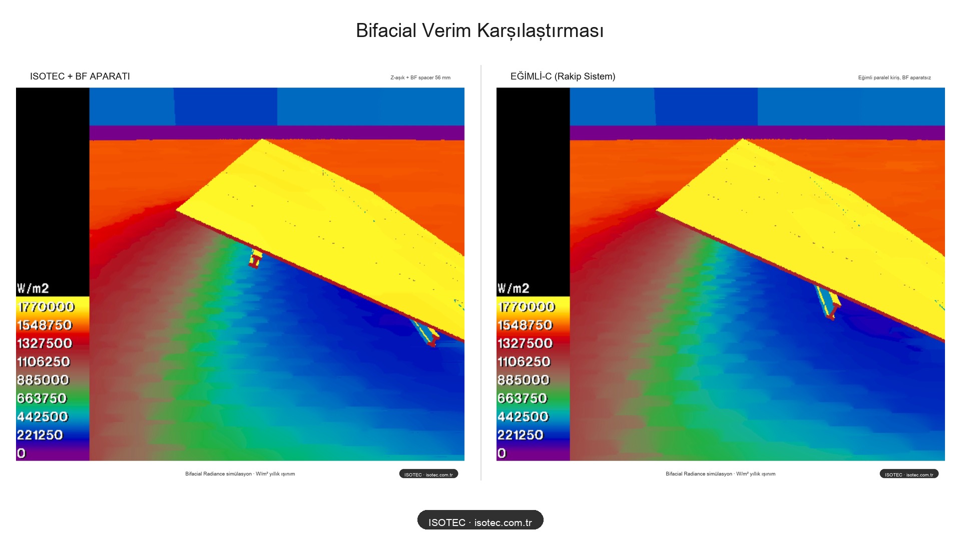
Numerical results
| System | Bifacial Gain | Shadow Line | Cost |
|---|---|---|---|
| Inclined-C (Competitor) | ~%18-20 | 1 big | 💰💰💰 High |
| ISOTEC + BF Adapter | %18 | 2 small | 💰 Economical |
| ISOTEC (without BF adapter) | ~%10-12 | 2 nearby shadows | 💰 Lowest |
The same bifacial production, shorter beam, less steel, faster assembly. The cost difference is significant at the field scale.