
ISOTRAP XLA
- An economical and reliable solution.
- Front-adhesive EPDM tape
- Possibility of using longitudinal profiles (1050-6050 mm)
- 1.4 - 2.4 kg/m² lightweight design
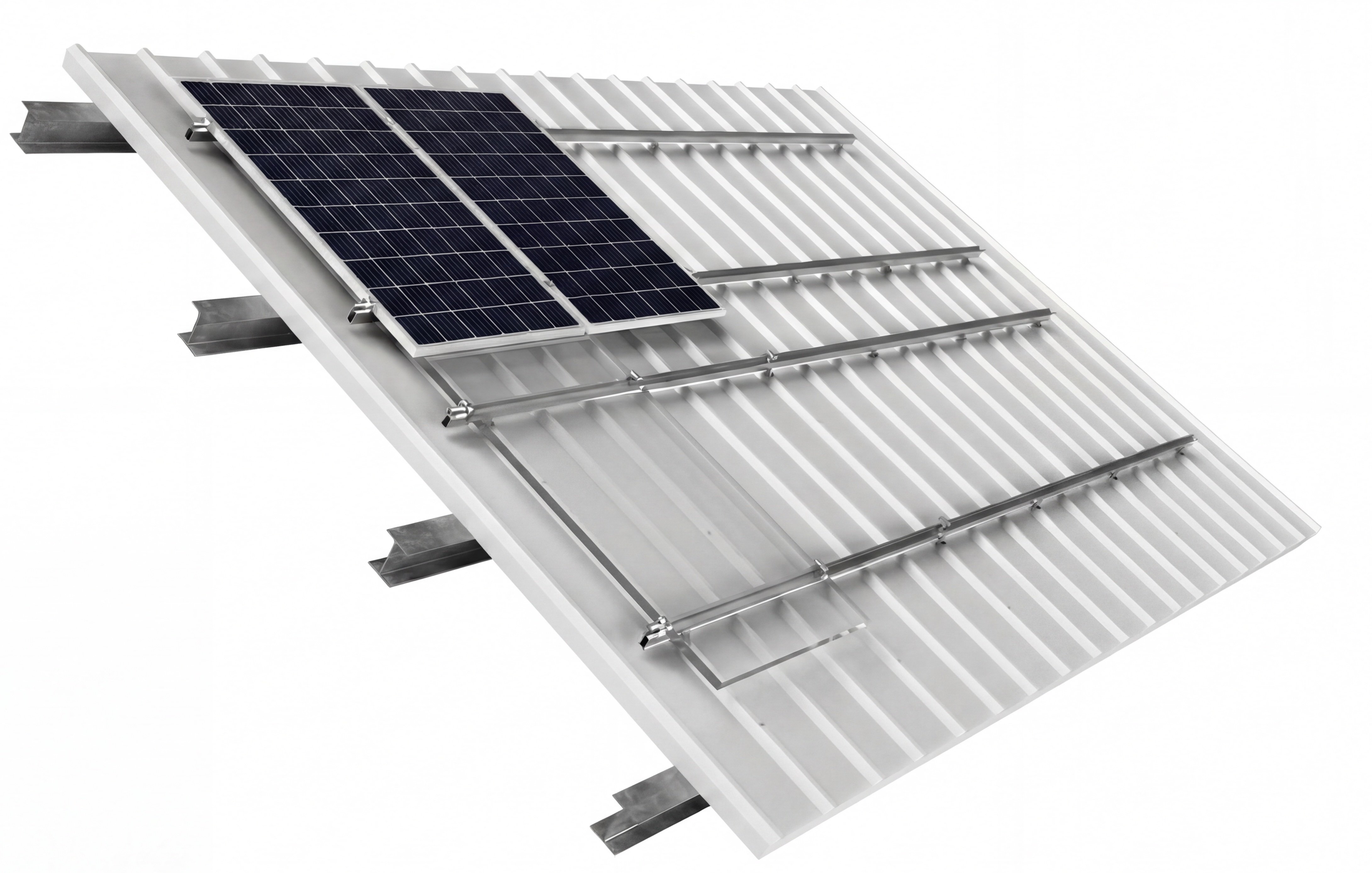
What is ISOTRAP XLA?
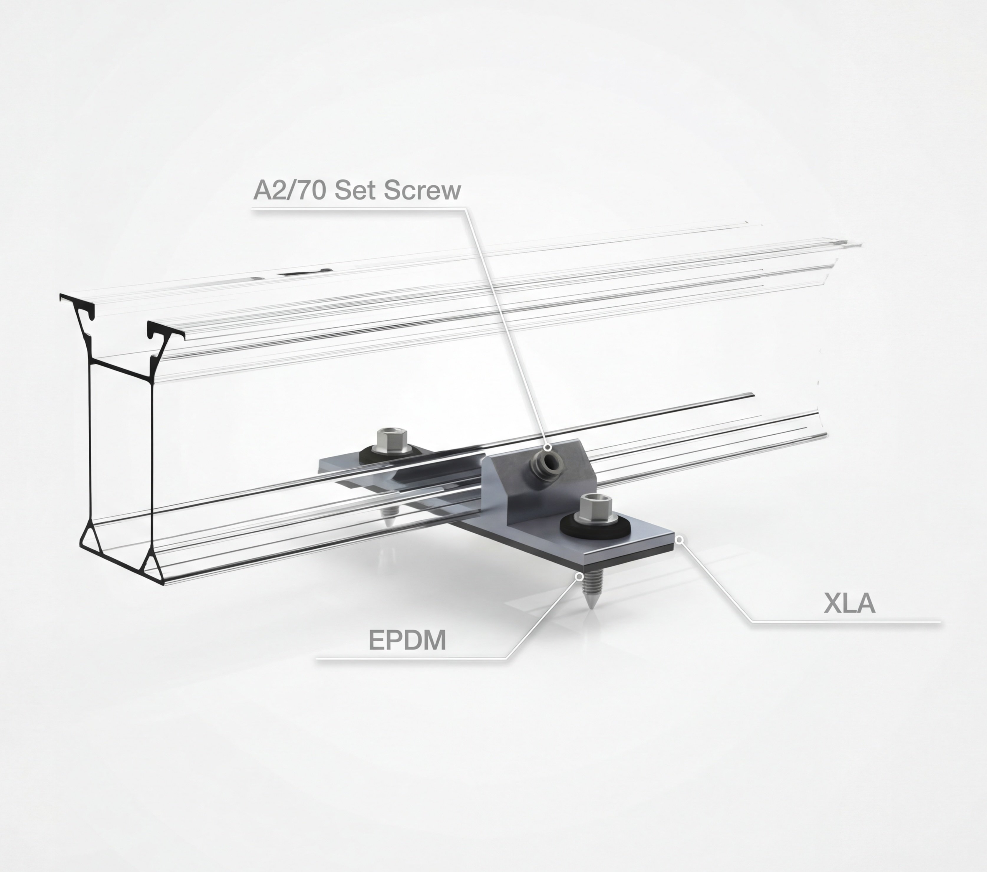
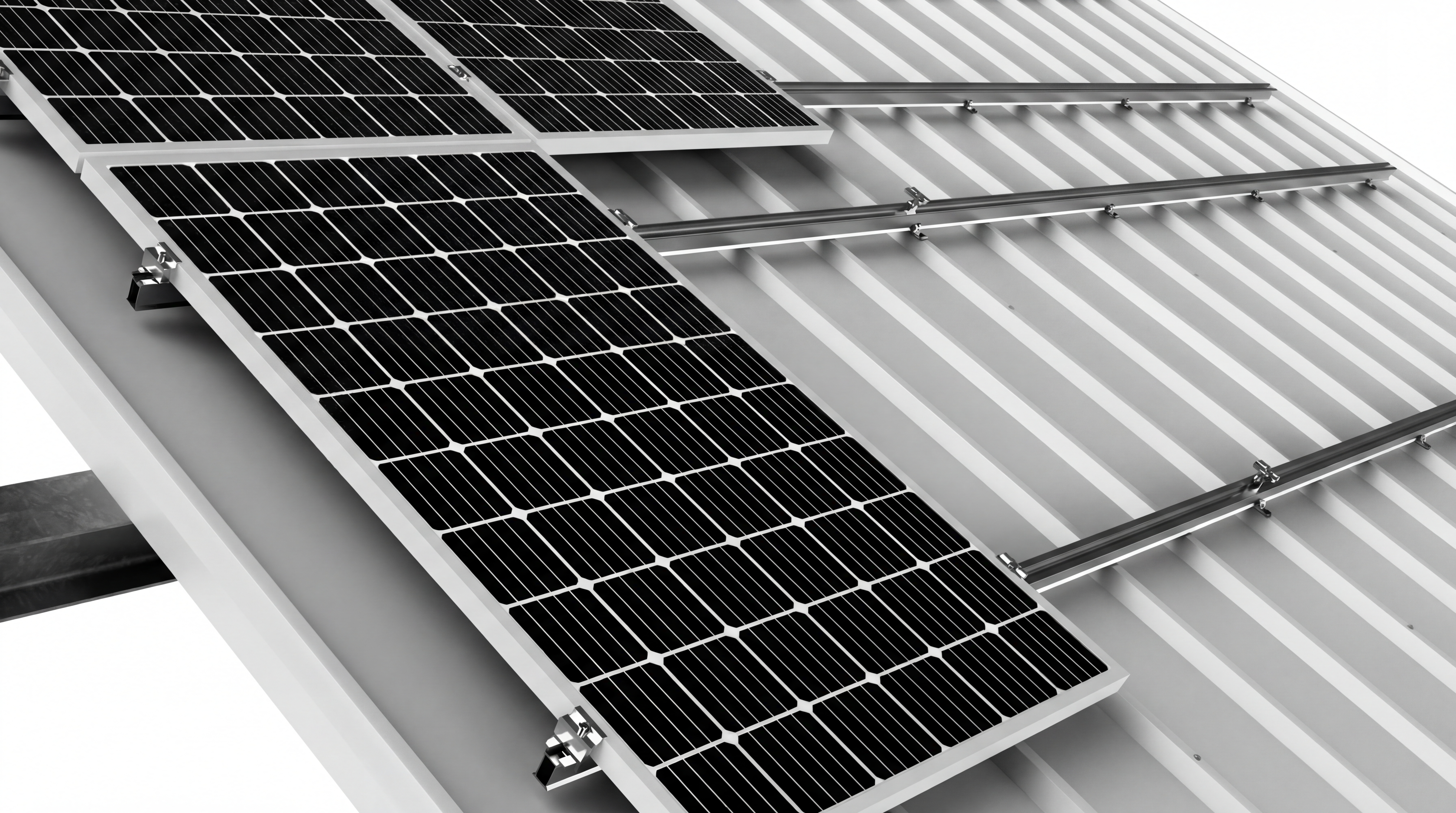
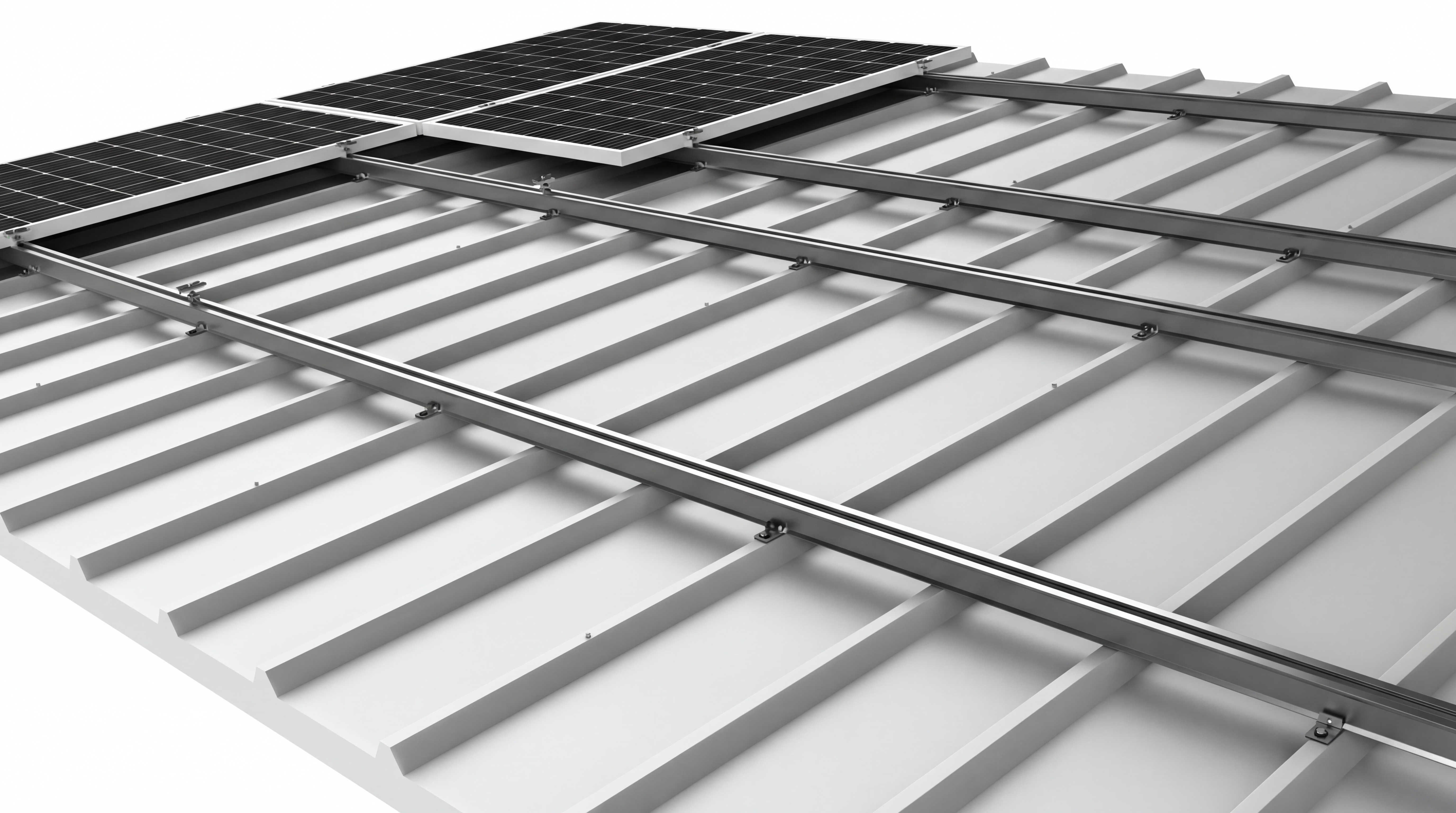
ISOTRAP XLA is a professional mounting system designed for solar panel installation on trapezoidal and sandwich-clad industrial roofs, utilizing full-length rails. Unlike other ISOTRAP systems, XLA brackets combine with ISOBEAM profiles to provide added strength to your roof.
XLA aparatlarının üzerinde önden delinmiş delikler sayesinde uygulama esnasında çapak oluşturulmaz, alt kısmında önden yapıştırılmış EPDM contalar sayesinde suyun çatı kaplamasının altına sızmasını engeller. Contalı sivri uçlu vidalar veya su geçirmez perçinler ile %99.9 sızdırmazlık garantisi sunar.
Dört farklı ISOBEAM profil yüksekliği (30, 45, 60, 85 mm) ile sıcak bölgelerde optimum hava sirkülasyonu sağlanırken, ISOBEAM Connector aparatları ile profiller uç uca birleştirilerek sınırsız uzunlukta ray oluşturulabilir. EasyClamp universel kelepçe sistemi ile %25'e kadar hızlı kurulum avantajı sunar.
Technical Data
| Area of Use | Trapezoidal and sandwich-type pitched roofs |
| Panel Size (L) | 1,500 - 2,384 mm |
| Panel Size (W) | 990 - 1,330 mm |
| Panel Size (H) | 30 - 45 mm |
| Profile Size Options | 1,050 - 6,050 mm |
| Profile Height Options | 30 / 45 / 60 / 85 mm |
| Fixing | Sealed pointed screw / Waterproof rivet + XLA fitting |
| Profile / Rail | Aluminum 6063-T66 |
| Handcuff | Aluminum 6005-T6 |
| Gasket | EPDM Rubber |
| Fasteners | Stainless Steel A2-70 & Bimetal |
| Weight | 1.4 - 2.4 kg/m² |
| Residential | Horizontal and Vertical |
System Components
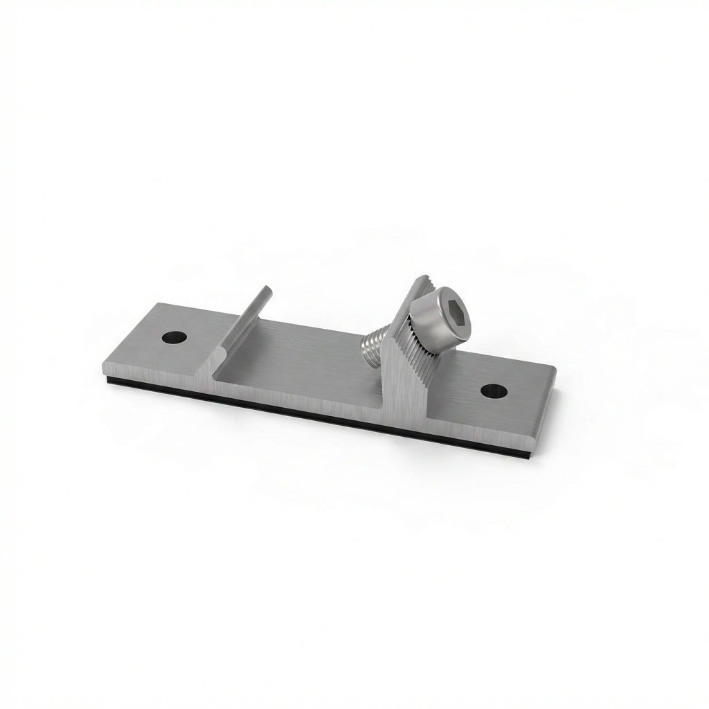
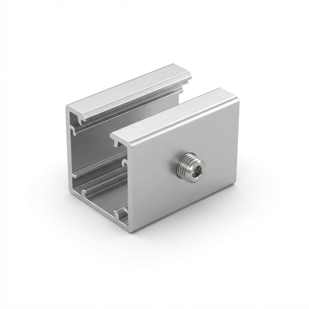
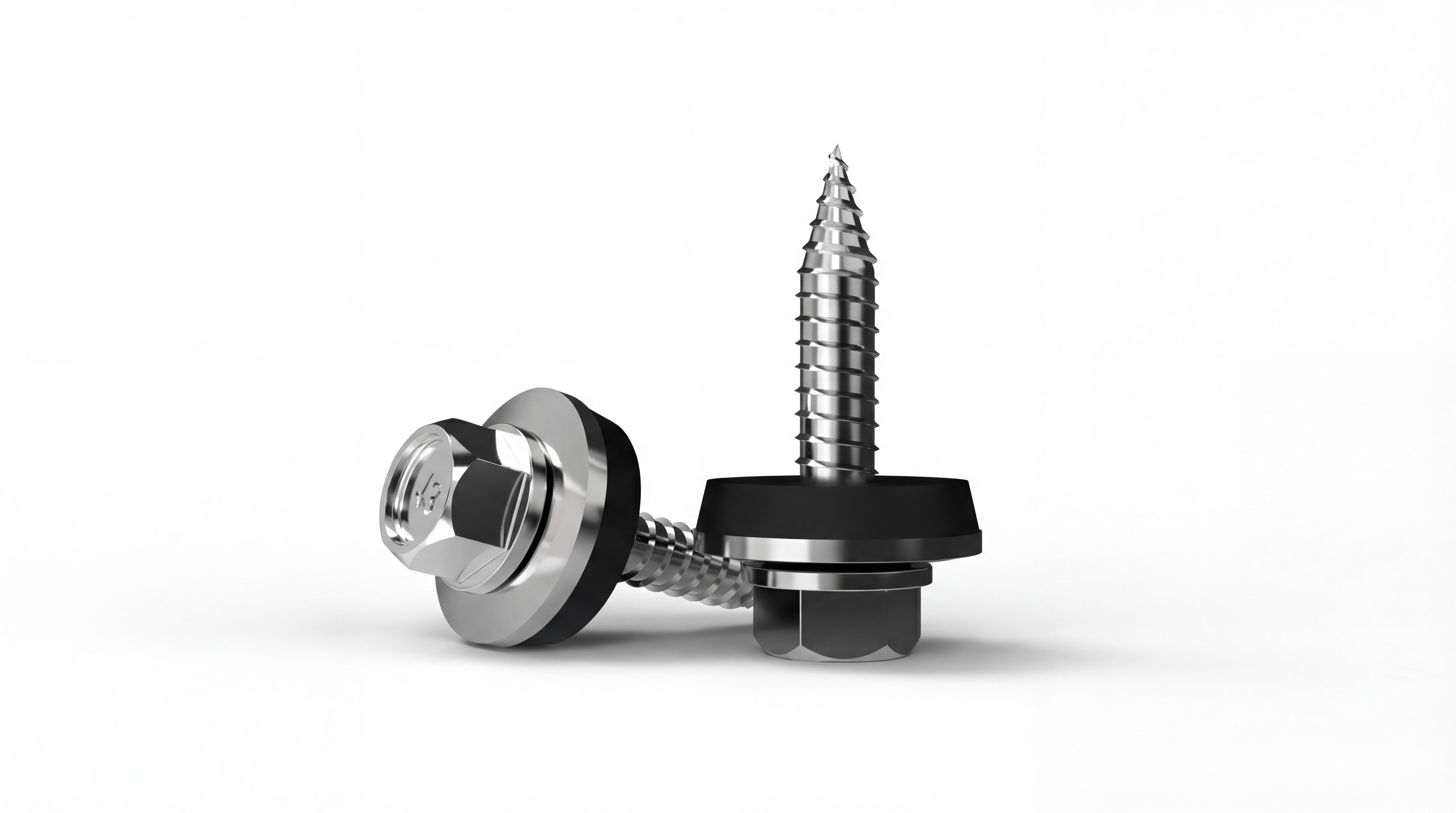
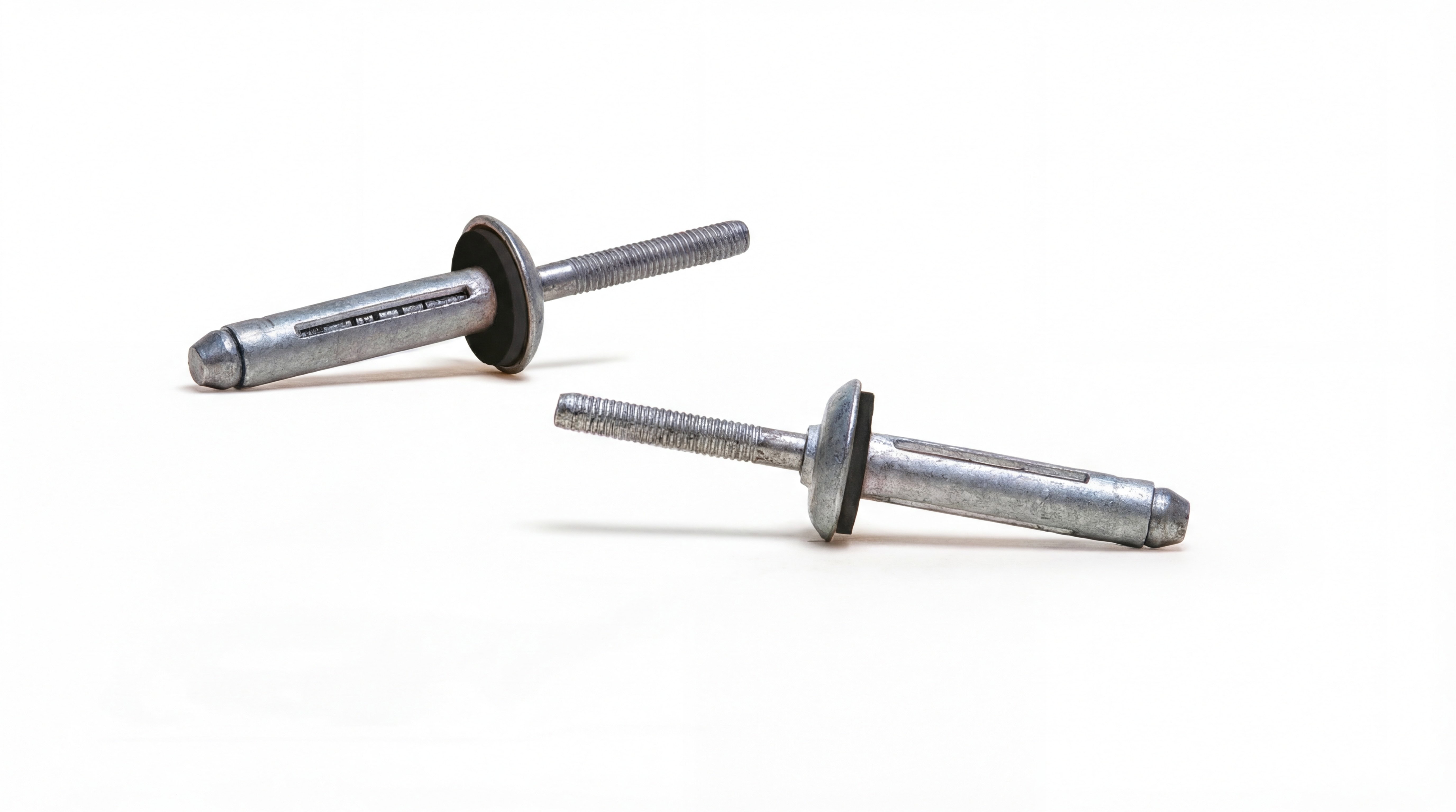
Main mounting bracket. Features pre-drilled holes and EPDM tape protection for protection against moisture and leaks. Secured to the rib with gasketed screws or rivets.
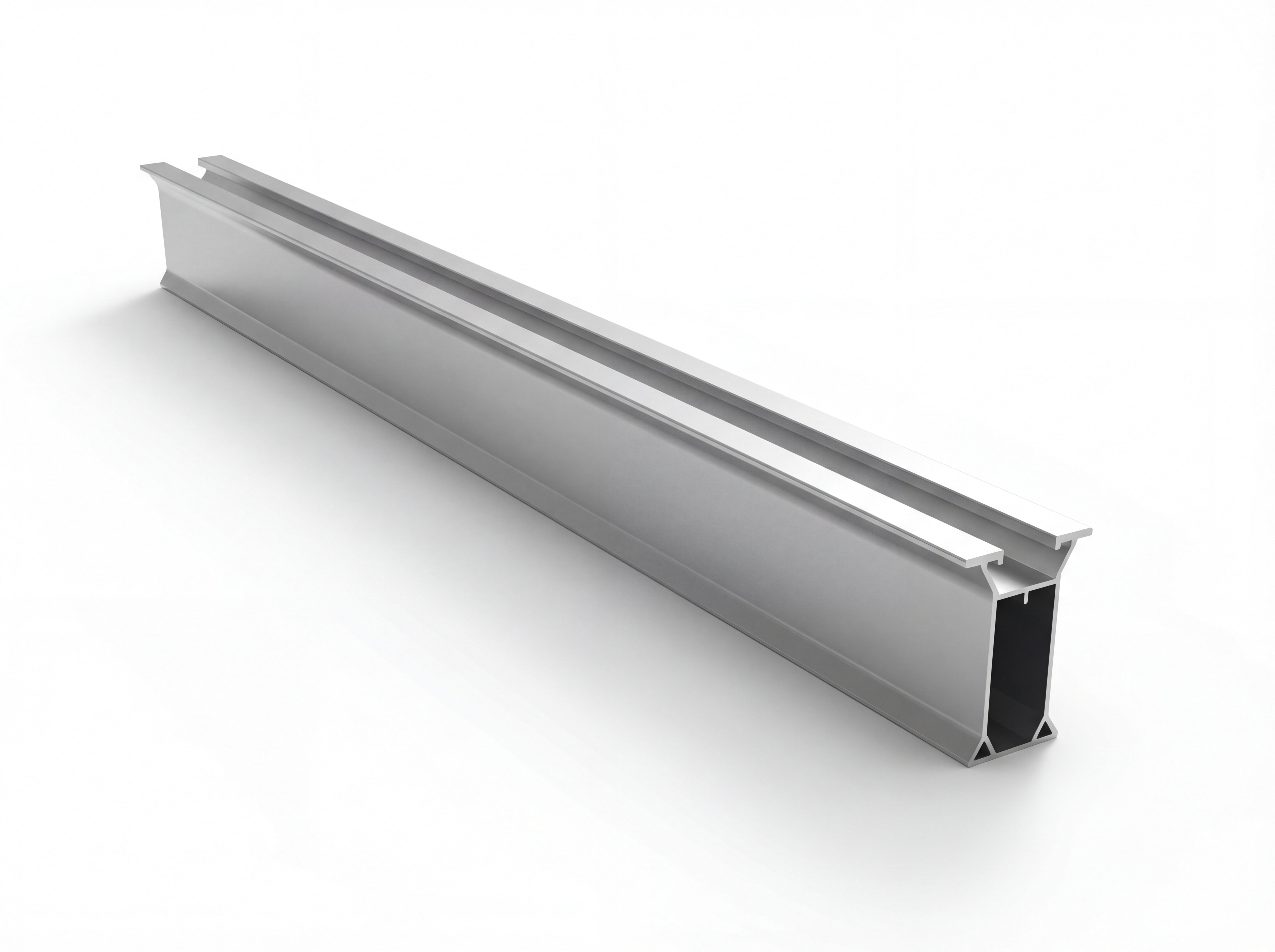
Panel carrier main rail profile (AL 6063-T66). Available in 1050-6050 mm length and 30/45/60/85 mm height options. Fits into the channel of the XLA bracket.
A connector for joining two ISOBEAM profiles end-to-end. It is inserted into the profile and secured with a self-tapping screw.
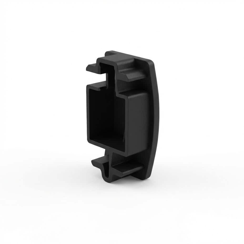
It provides both protection and aesthetic appeal by covering the exposed end of the profile.
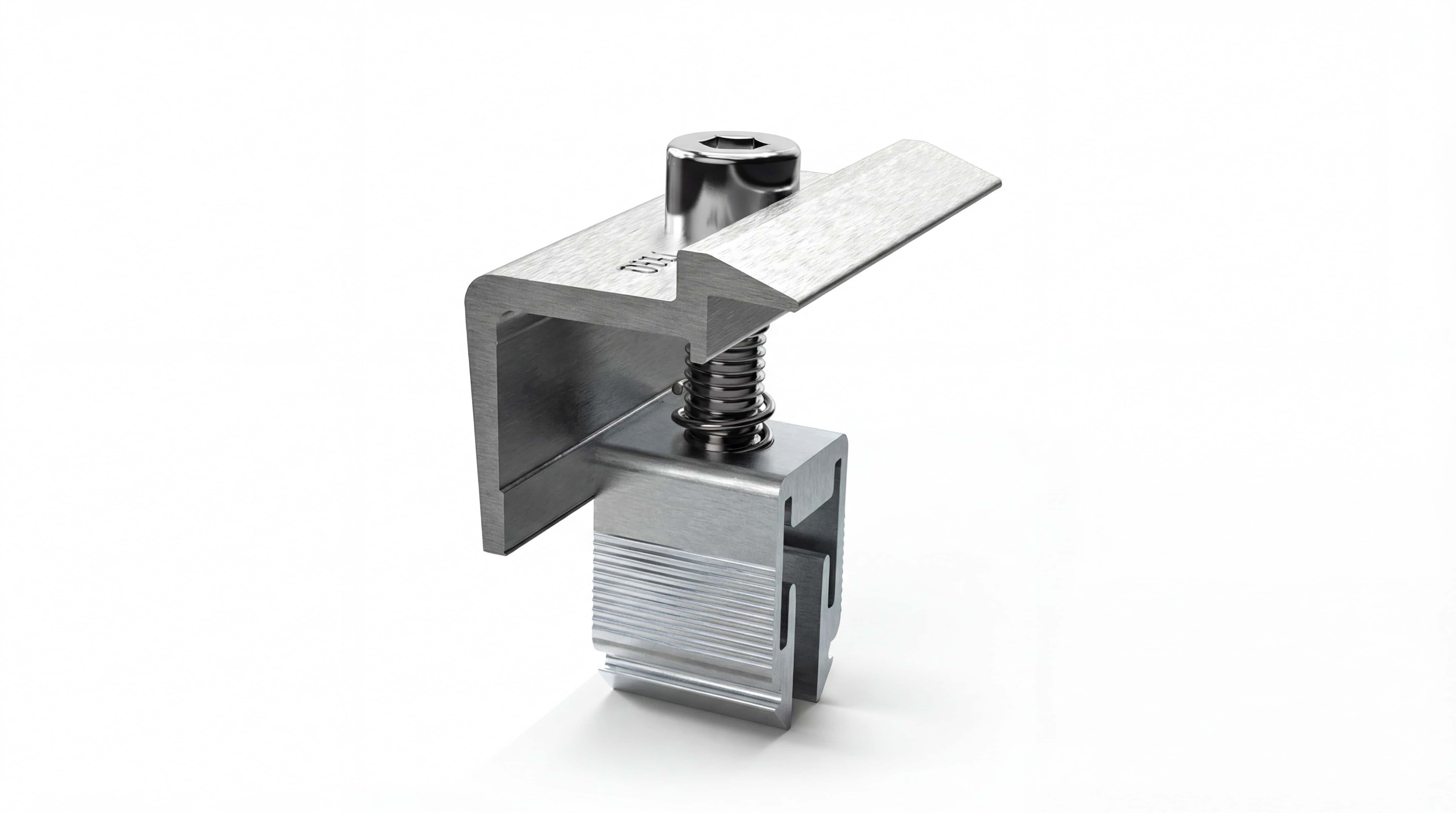
Universal end clamp for the exposed edges of panels. Compatible with all PV modules with a 30-45 mm frame.
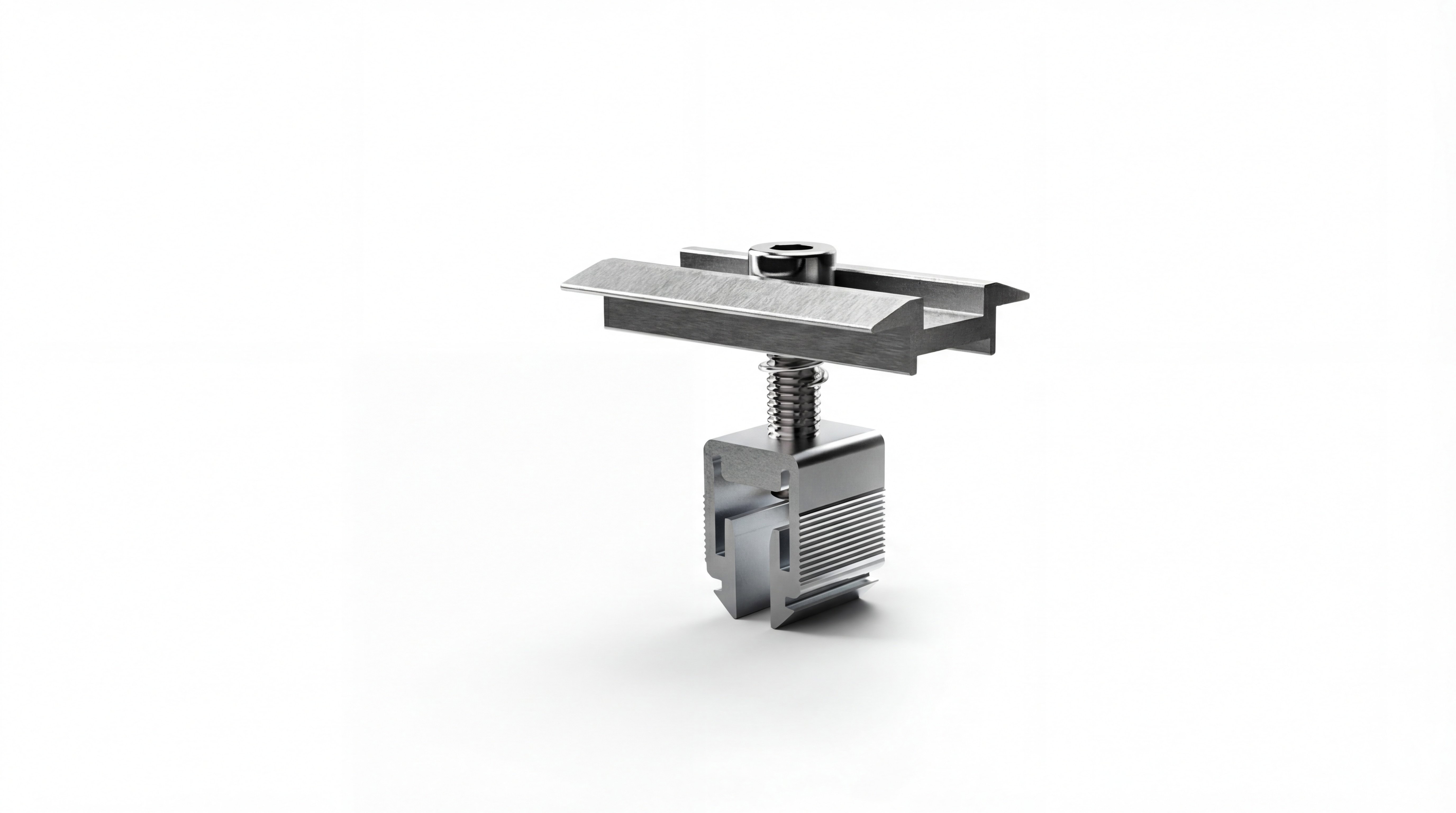
Universal center clamp for edges between two panels. Compatible with all ISOTEC systems.
The sealed screw prevents leakage, securely fastening the XLA bracket to the roof and ensuring maximum durability.
EPDM koruyucu ile %99.9 sızdırmazlık garantili özel perçin. XLA aparatını sabitleyerek maksimum dayanım sağlar.
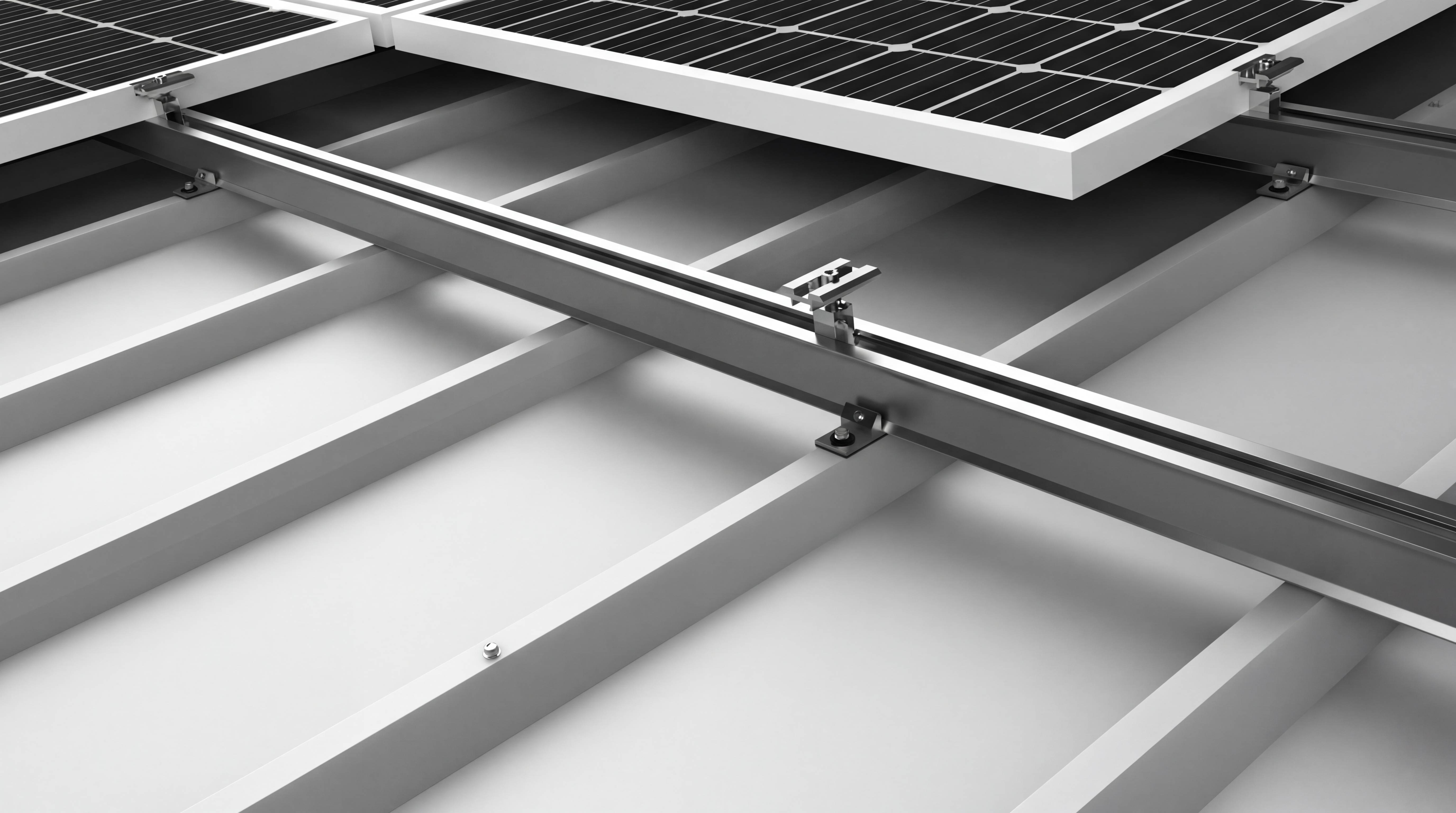
Easy Assembly
-
1Marking and Placement The mounting spacing for the ISOTRAP XLA brackets is determined and marked on the roof surface according to the panel layout. The XLA brackets are then placed on top of the ribs.
-
2XLA Fixation Sealed pointed screws or waterproof rivets are mounted vertically to the roof at the points where they align with the corrugation. The opening of the seal should be observed.
-
3ISOBEAM Profile Assembly ISOBEAM profiles are placed into the channel of the ISOTRAP XLA bracket, and the profile is secured by tightening the Allen screw located on the bracket.
-
4Profile Merging and Cover For system continuity, the ISOBEAM Connector adapter is inserted into the profile at the edges where the two profiles meet and secured with self-tapping screws. ISOBEAM Caps are fitted to the ends.
-
5Panel Assembly At the beginning and end of the system, the EasyClamp End is placed into the channel of the ISOBEAM profile. The solar panel is installed into the system and secured by tightening the EasyClamp End.
-
6Intermediate Clamp and Completion EasyClamp Mid adapters are added to the space between the two panels, and after the two panels are placed into the system, they are tightened and secured. Thus, the system is completed.
Technical Documents
Download all technical documentation for the product.
Let's work together to determine the most suitable ISOTRAP XLA configuration for your project.
BF Device · Bifacial Shading Advantage
There are two different approaches in the industry. Why is ISOTEC's BF apparatus both economical and high-performing?
Why is shading important in bifacial panels?
Bifacial (double-sided) solar panels generate electricity from both their front and back surfaces. The back surface captures radiation reflected from the ground and coming from the side edges — typically. %15-20 ek üretim provides.
The critical point: Any part (purlin, beam, cable) that blocks light falling on the back surface of the panel → on the back surface shadow lines It creates a shadow, and the cells under this shadow lose productivity. Between the purlin and the panel... distance and the purlin cross-sectional area These are the determining parameters.
Therefore, to get the most out of a bifacial investment, the design of the mounting system is critical.
Two Design Philosophies in the Industry
There are two main approaches in the industry to reduce bifacial shadowing:
Inclined C-Beam competitors
The beam runs parallel to the panel at the same angle. A single long C-profile provides grip along the panel.
- ✓ Minimal shade, high bifacial yield.
- ✗ Long steel beams, high material costs.
- ✗ In sloping structures, column heights vary.
- ✗ Tolerances are tight, assembly takes a long time.
Vertical Beam + Horizontal Z-Purlin ISOTEC + BF
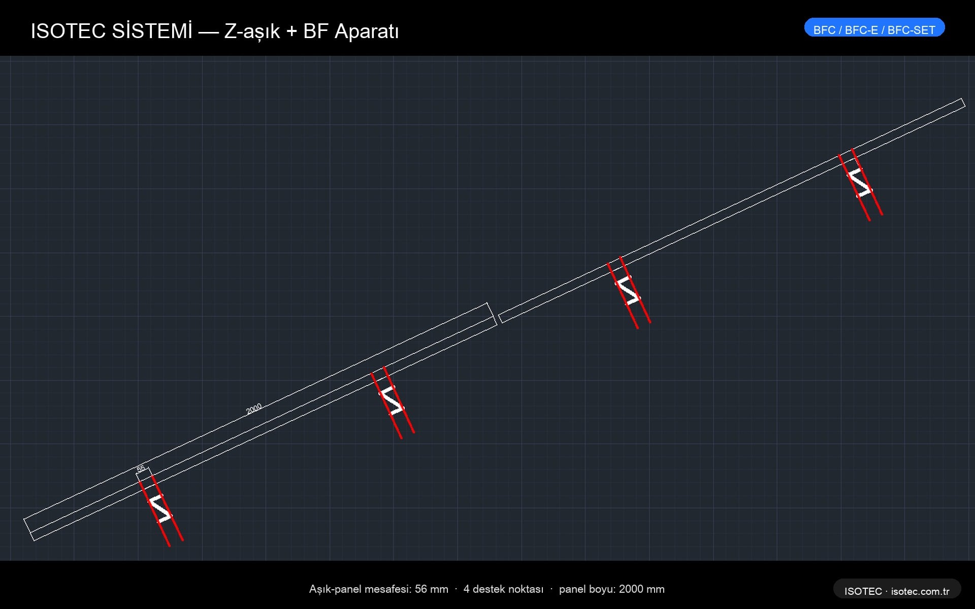
The beams are vertical (perpendicular to the ground, short). The Z-profile purlins extend horizontally. A BF 56 mm spacer is inserted between the purlin and the panel.
- ✓ Low steel content, quick assembly, economical.
- ✓ Bifacial performance with BF apparatus and Inclined-C equal
- ✓ Standard column, easy supply.
- ✓ Slot design compatible with thermal expansion.
CAD comparison — purlin-panel distances
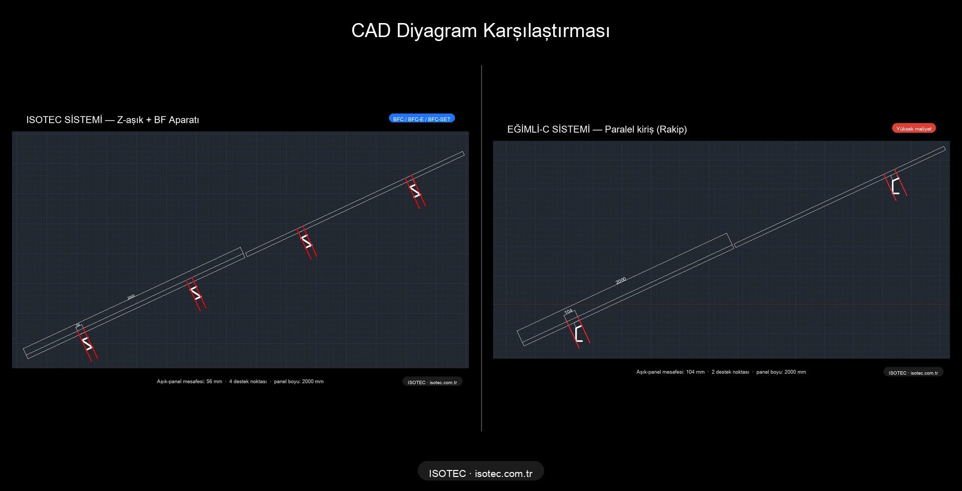
How does the BF adapter work?
The ISOTEC BF adapter is a device placed between the Z-shaped purlin and the bottom surface of the panel. spacer + clamp systemIt maximizes the radiation falling on the back surface of the panel by creating a distance of 56 mm.
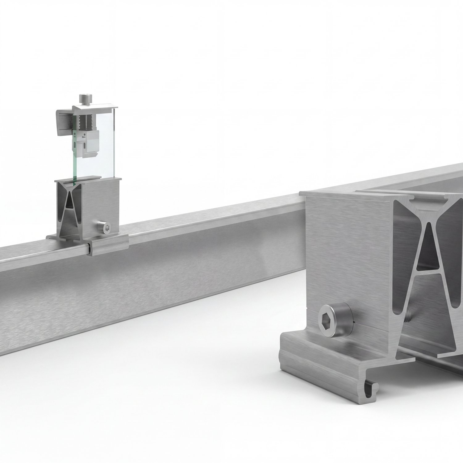
Design features
- Spacer body: EN AW-6005A T6 anodized aluminum (3.0 mm wall)
- Distance: The distance between the purlin's top surface and the panel's bottom surface is 56 mm.
- Slot design: Panel thermal expansion accommodated (±2 mm tolerance)
- Screw: Stainless steel A2 M8×40 hexagonal
Clamp variations
| Code | Medicine | Use |
|---|---|---|
| BFC | Glass-to-glass edge | For frameless glass-to-glass panels at panel edges. |
| BFC-E | Medium grip | Center panel, shared grip, frameless. |
| BFC-SET | Complete set | All components are pre-packaged, quick assembly. |
CAD details — ISOTEC system
Bifacial Radiance Simulation Results
The results are from NREL's (US National Renewable Energy Laboratory) open-source program. Bifacial Radiance This was achieved using a Python library. A scanner-based radiation calculation is performed that accurately reflects field conditions.
Heat map comparison
Warm (yellow) colors indicate high irradiation (1.77 MWh/m² annually), while cool (blue) colors indicate shaded areas. In both systems, the front surface of the panel (the upper yellow area) receives homogeneous irradiation; the difference is the panel. on the back surface It is seen.
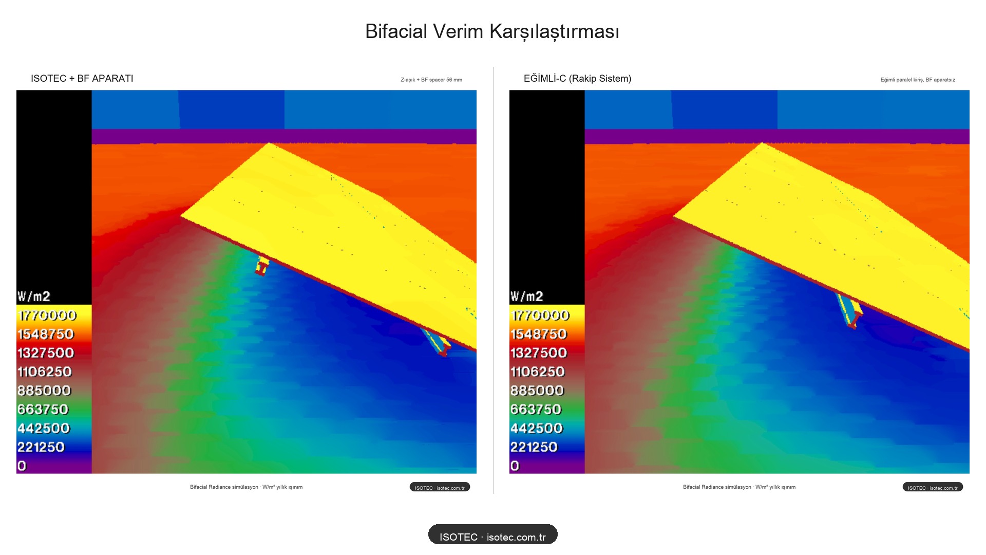
Numerical results
| System | Bifacial Gain | Shadow Line | Cost |
|---|---|---|---|
| Sloping-C (Opponent) | ~%18-20 | 1 big | 💰💰💰 High |
| ISOTEC + BF Adapter | %18 | 2 small | 💰 Economical |
| ISOTEC (without BF adapter) | ~%10-12 | 2 nearby shadows | 💰 Lowest |
The same bifacial production, shorter beam, less steel, faster assembly. The cost difference is significant at the field scale.