ISOFLAT S13
- IFI wind tunnel test approved (Report No: IEI01-2)
- Securing with ballast without drilling into the roof.
- 13° south slope — maximum energy production.
- Pre-assembled kits with single tool installation.
- %100 yerli üretim, 12 yıl sistem garantisi
What is ISOFLAT S13?
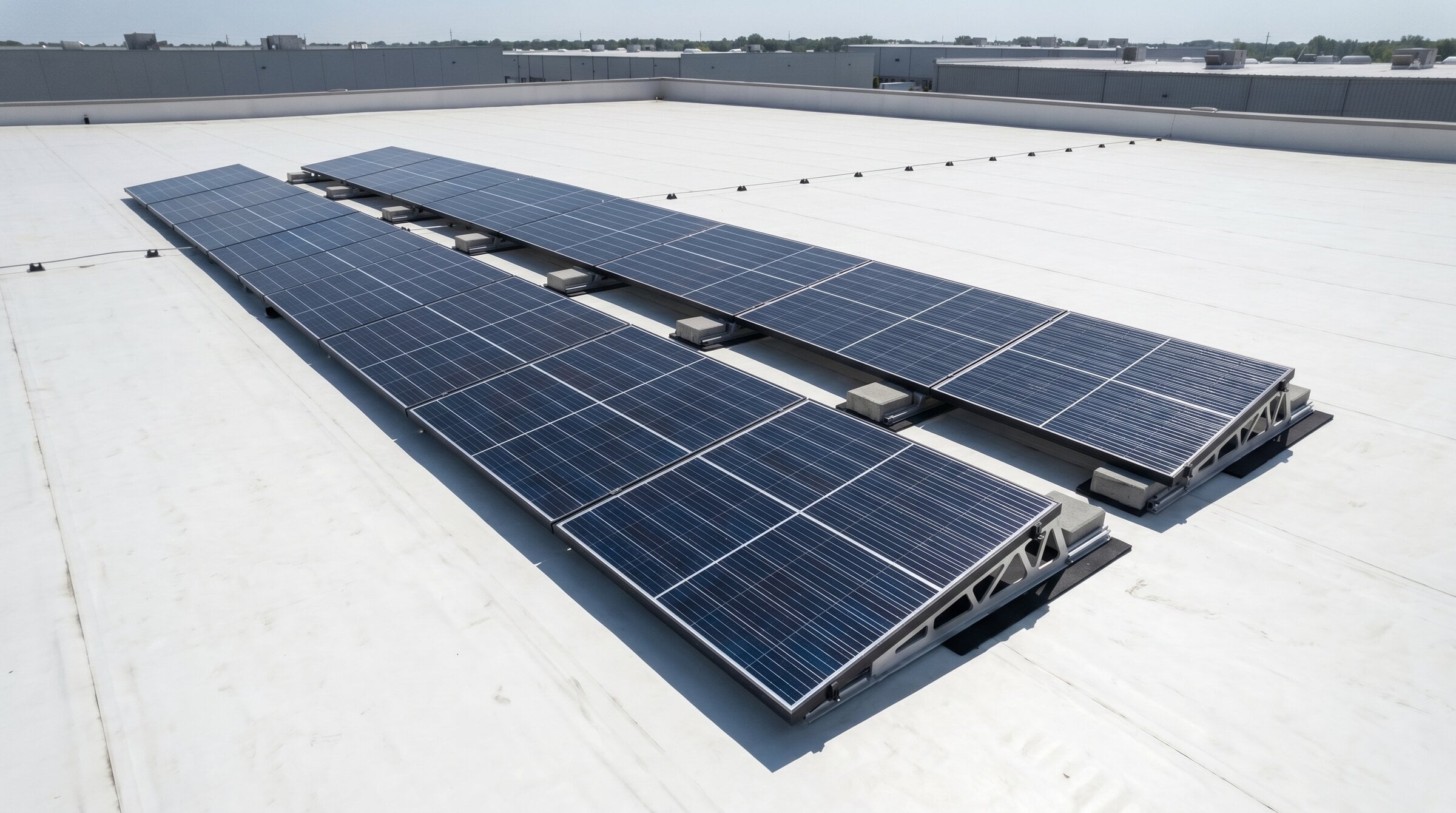
ISOFLAT S13 is a single-sided (asymmetrical) flat roof mounting system that installs solar panels on flat roofs with a 13° south slope. It is designed for flat concrete roofs, gravel roofs, and membrane-covered roofs; the system is fixed to the roof using ballast (weights) without drilling any holes in the roof.
The system consists of the TFX-1400 short main rail, ISOFLAT BS3 rear support, ISOFLAT Connector 150 and Connector 350, EasyClamp Mid/End clamps, RUA.3 standard wind deflector, EPDM buffer membrane, and stainless steel A2-70 fasteners. The profiles and clamps are made of Aluminum 6063-T66 alloy, conforming to EN ISO standards.
A 13° south slope ensures maximum energy production in a single direction; this orientation optimizes annual production. The system is divided according to thermal expansion, with each row being a maximum of 15 m and a minimum distance of 550 mm from the roof edge. Reliable installation is ensured by design data tested in the IFI Institut für Industrieaerodynamik (Aachen, Germany) wind tunnel in accordance with EN 1991-1-4.
Science Guarantees It — IFI Aachen Wind Tunnel Test
Not a guess, but a measurement. The ISOFLAT S13 system was tested at an independent institute in Germany.
The actual wind load acting on a solar system fixed with ballast on a flat roof cannot be determined by desk calculations; it must be measured in a wind tunnel. The ISOFLAT S13 was tested in the wind tunnel of the IFI Institut für Industrieaerodynamik GmbH (part of the University of Aachen, Germany) in a 13° south-tilting array configuration.
The test, in accordance with EN 1991-1-4:2005 and DIN EN 1991-1-4/NA:2010-12 standards, produced pressure coefficients for buildings with roof slopes up to 10° and heights up to 50 m, for different range zones and effective wind areas.
Result: For each project, site-specific ballast calculations are designed according to EN 1991-1-4 using peak velocity pressure (qp) and report data. This ensures the system is delivered verified for each site — the risk of blow-off is mitigated by measurement, not by guesswork.
IFI Test Report — IEI01-2 (PDF)Flat roof systems that haven't undergone wind tunnel testing behave like this in the field. This is not the place for ISOFLAT S13 — this is the IFI testing laboratory.
Technical Data
| Area of Use | Flat concrete roofs, gravel roofs, membrane roofs |
| Angle of Slope | 13° south (8°–13° depending on panel size) |
| Orientation | One-way (Single) — faces south. |
| Panel Size (L) | 1,640 – 2,400 mm |
| Panel Size (W) | 990 – 1,303 mm |
| Panel Size (H) | 30 – 45 mm |
| Panel Placement | Horizontal (landscape); short or long edge mounting. |
| Fixing | Ballast / IMC / Anchor |
| Main Rail | TFX-1400 (short rail) |
| Profile / Clamp | Aluminum 6063-T66 |
| Ground / Between Rails | SBR Rubber Membrane |
| Fasteners | Stainless Steel A2-70 |
| Maximum Series Length | 15 m (thermal expansion limit) |
| Roof Edge Distance | Minimum 550 mm |
| Roof Slope Limit | >When using %3, fixing to the parapet with steel cable. |
| Maximum Building Height | 20 m |
| Standard | EN 1991-1-4 (Eurocode 1) + IFI wind tunnel (IEI01-2) |
| Warranty | 12-year system warranty |
System Components
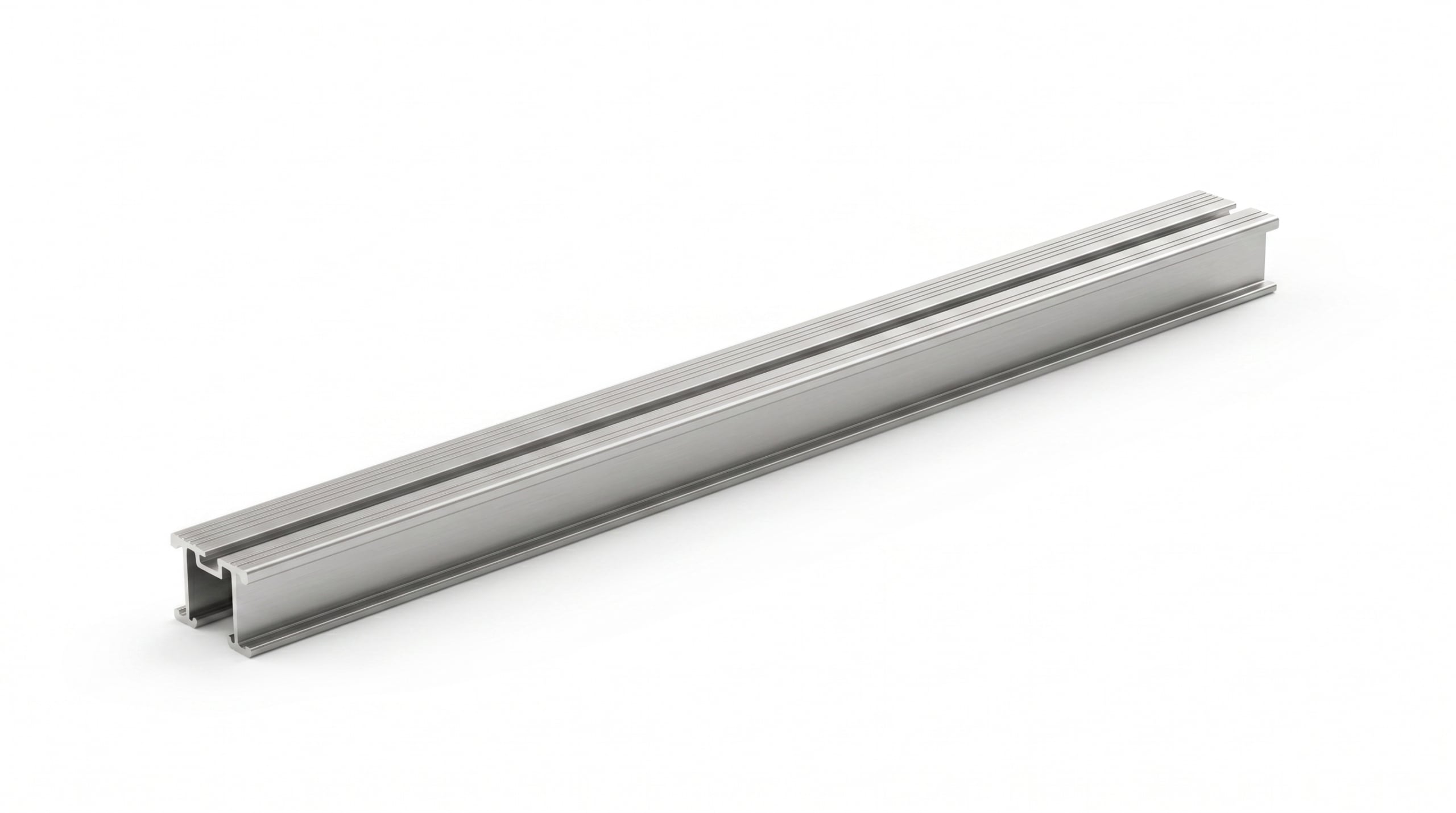
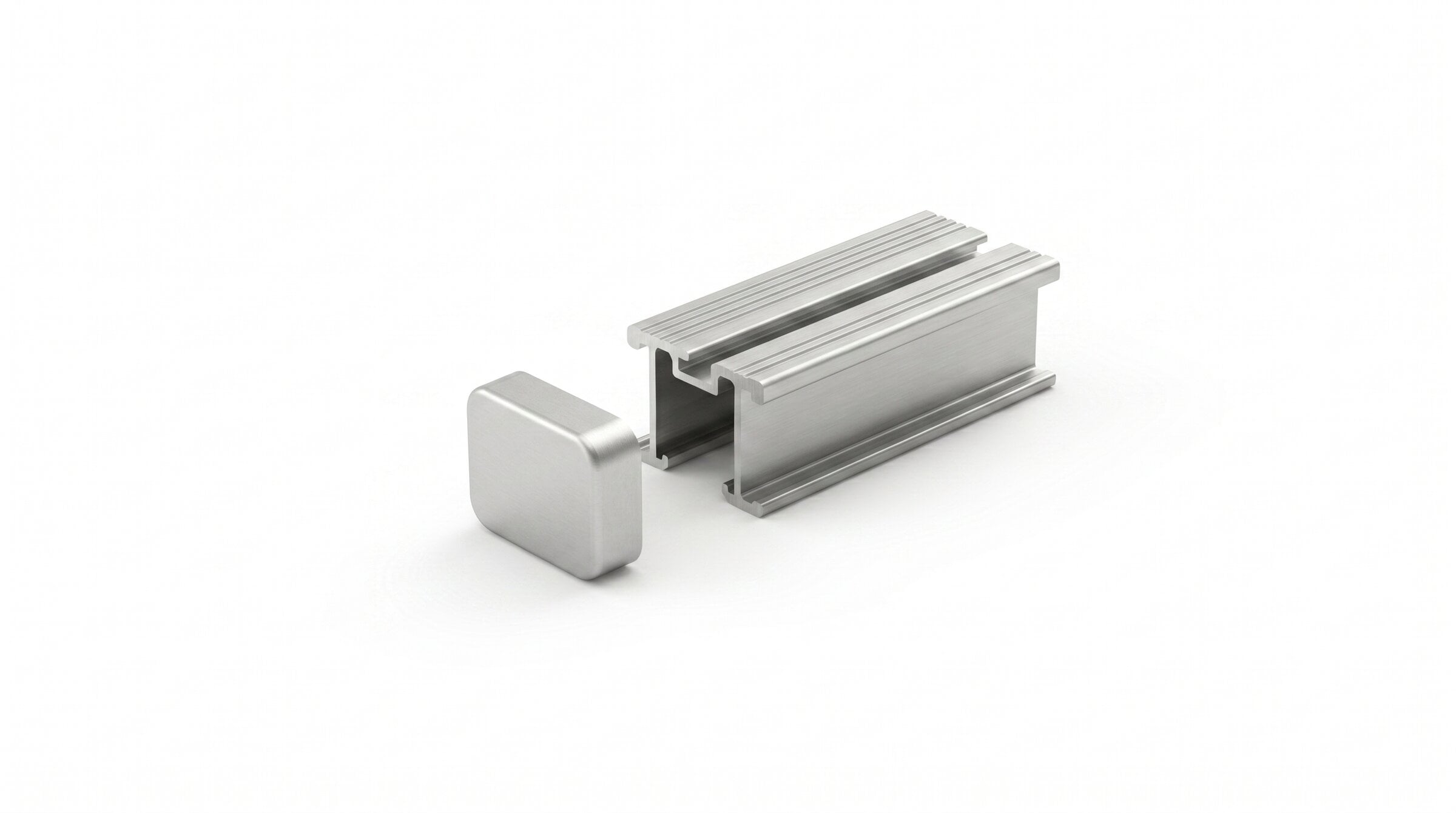
1,400 mm long aluminum short main rail. Guide strips on the top surface facilitate mounting on the long or short edge of the panel. Aluminum 6063-T66.
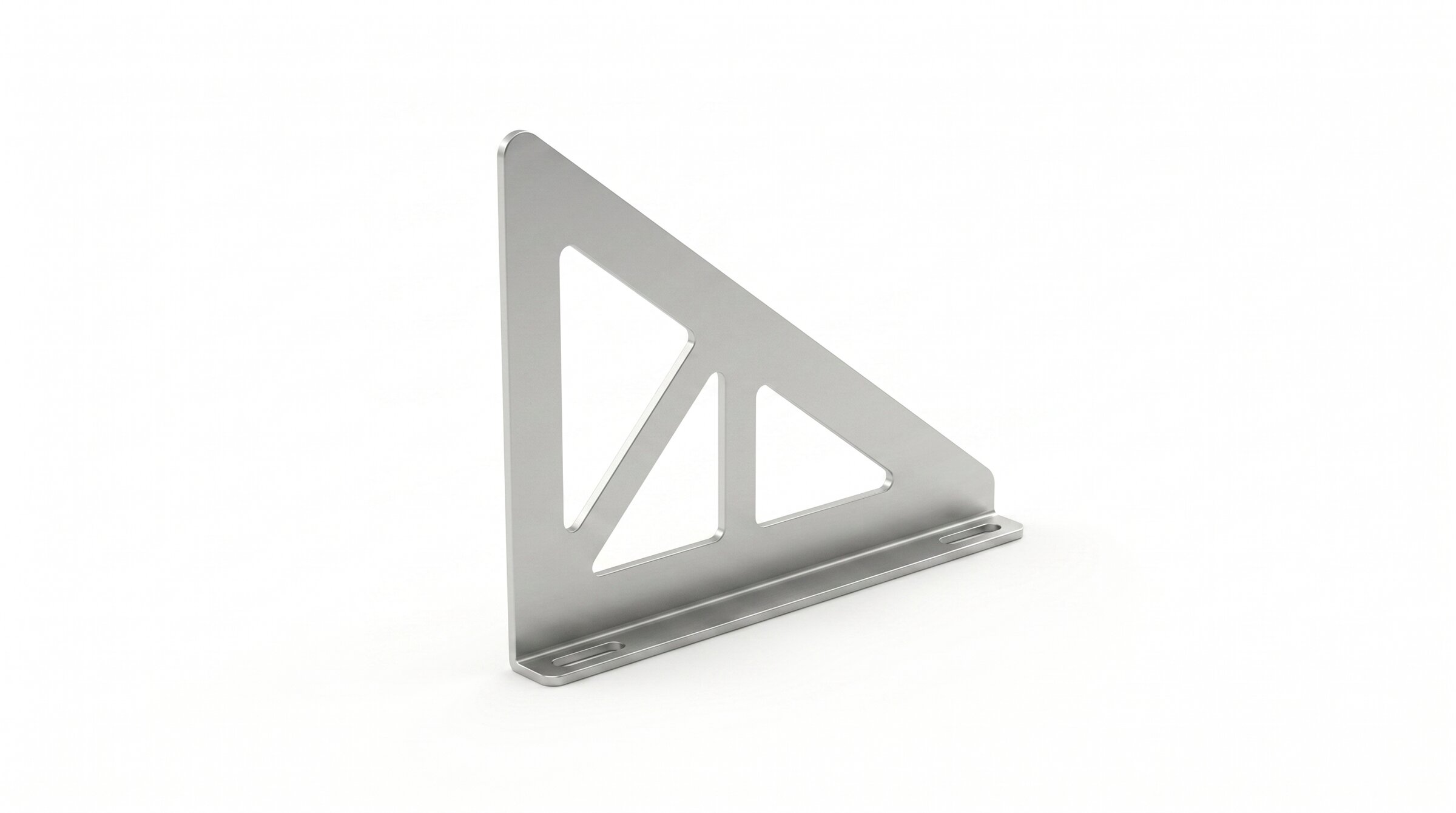
The triangular rear support supports the panel at a 13° south incline. It is placed in the guide according to the panel size, rotated 90° onto the rail, and secured with T-head bolts.
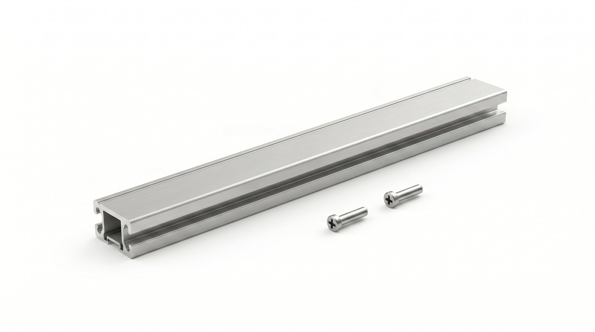
A connector that connects and secures rail sets with pins. The standard 150 mm version and the 350 mm long (Connector Long) version are used for panels with widths ≥ 1040 mm.
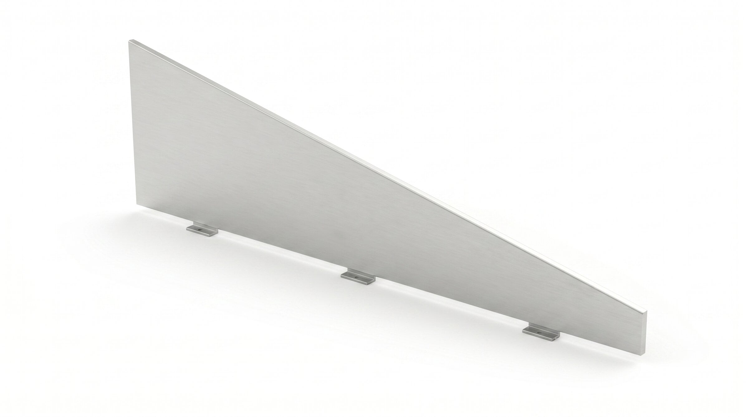
Side wind deflector, standard in ISOFLAT S13. It directs wind pressure at the ends of the chain, reducing lift. Features IFI test-approved geometry.
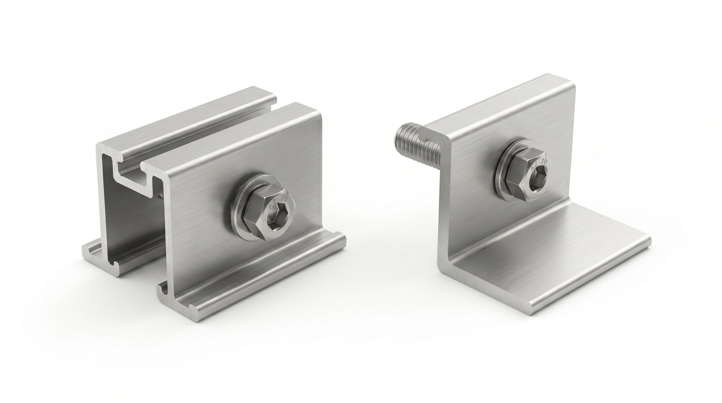
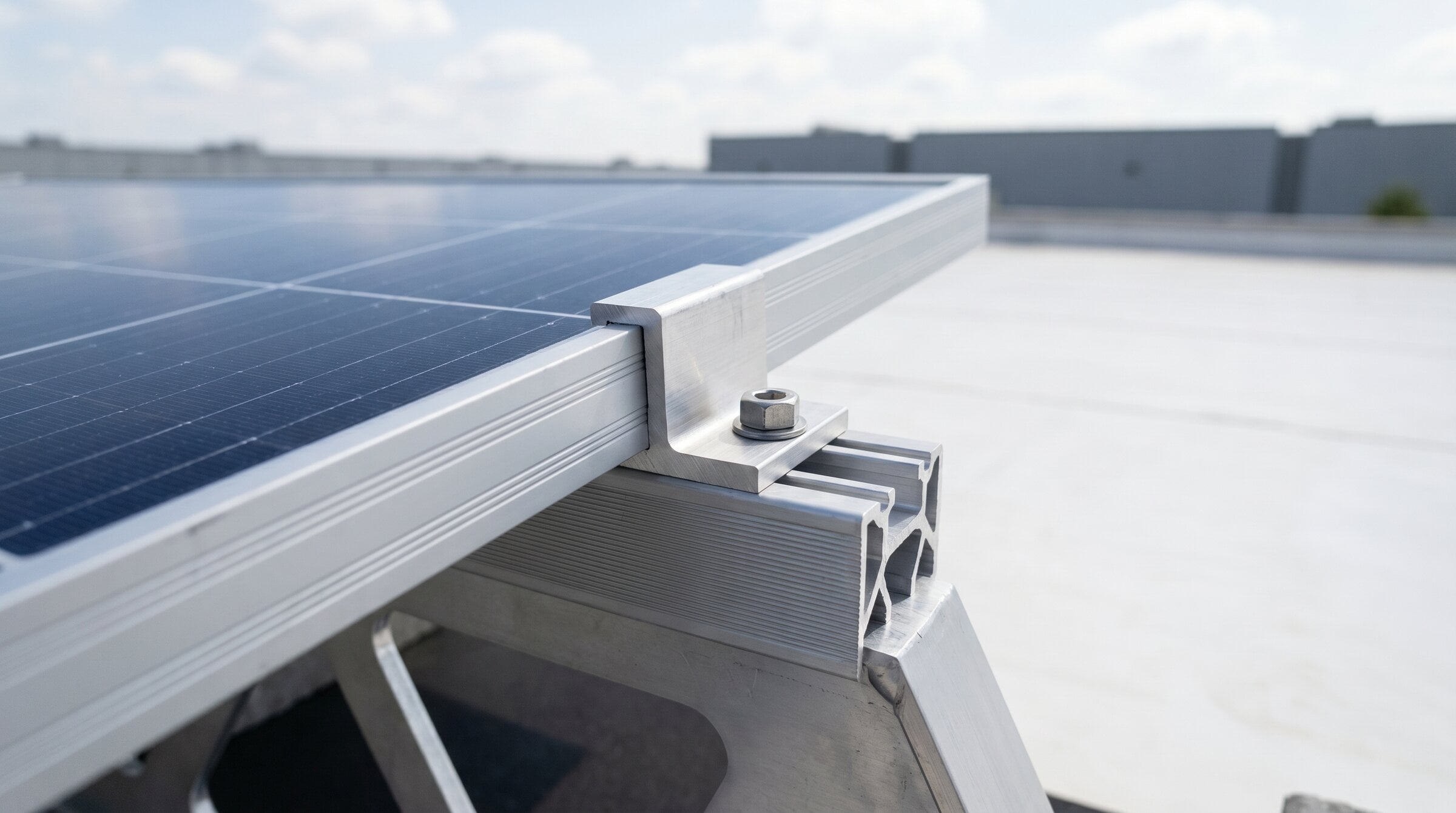
Universal mid-range and end clamps. Compatible with 30–45 mm frame PV modules. Works with all ISOTEC systems; Allen torque applied with a single tool.
Covers fitted onto the rail ends. Prevent dirt, water, and foreign objects from entering the rail; complete the edge appearance of the system.
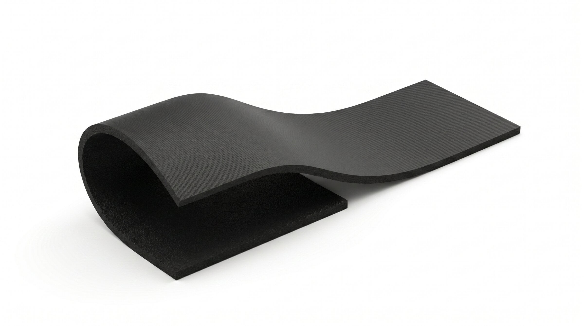
A rubber buffer laid between the rail and the roof surface. It protects the roof covering, prevents slipping, and tolerates surface irregularities.
Easy Assembly
-
1Roof Marking and Preparation According to the panel layout plan, the row positions are marked on the roof surface. A minimum distance of 550 mm is left from the roof edge; thermal expansion division is planned so that each row is a maximum of 15 m.
-
2SBR Membrane and Rail Placement SBR rubber buffer membrane is laid along the marked lines. TFX-1400 main rails are placed on top of the membrane; if necessary, they are joined end-to-end with ISOFLAT Connector 150 (or 350) and secured with pins.
-
3BS3 Rear Foot Positioning ISOFLAT BS3 rear feet are placed on the guide points on the rail according to the panel size. Each rear foot is rotated 90° onto the rail and tightened by inserting the T-head bolt into the rail.
-
4RUA.3 Wind Deflector and Cap Installation RUA.3 wind deflectors are fitted to the sides of the track, and Cap TFX caps are fitted to the track ends. The wind deflector positions are arranged in accordance with IFI design specifications.
-
5Panel and EasyClamp Installation The panels are fitted onto the top surface of the BS3 rear leg and the front of the TFX rail. EasyClamp End (outer edges) and EasyClamp Mid (between panels) clamps are installed; the Allen bolts are tightened to the appropriate torque value.
-
6Ballast Placement and Verification The ballast (weight) determined as a result of project calculations is placed directly on the rail. For medium/high loads, additional ballast is added between the rails; if the roof slope exceeds %3, fixing is done from the parapet with steel cables.
Technical Documents
Download all technical documentation for the product.
Let's determine together the most suitable ISOFLAT S13 configuration for your roof's string layout and wind load.
BF Device · Bifacial Shading Advantage
There are two different approaches in the industry. Why is ISOTEC's BF apparatus both economical and high-performing?
Why is shading important in bifacial panels?
Bifacial (double-sided) solar panels generate electricity from both their front and back surfaces. The back surface captures radiation reflected from the ground and coming from the side edges — typically. %15-20 ek üretim provides.
The critical point: Any part (purlin, beam, cable) that blocks light falling on the back surface of the panel → on the back surface shadow lines It creates a shadow, and the cells under this shadow lose productivity. Between the purlin and the panel... distance and the purlin cross-sectional area These are the determining parameters.
Therefore, to get the most out of a bifacial investment, the design of the mounting system is critical.
Two Design Philosophies in the Industry
There are two main approaches in the industry to reduce bifacial shadowing:
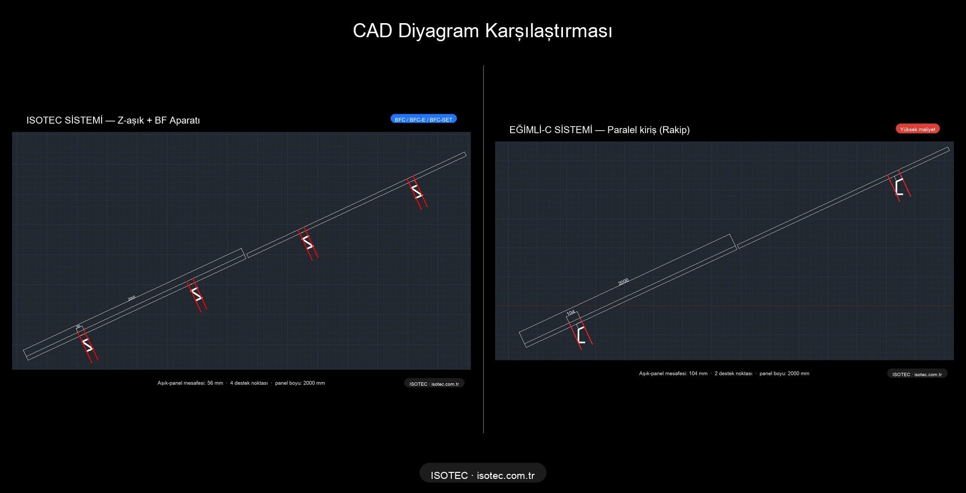
Inclined C-Beam competitors
The beam runs parallel to the panel at the same angle. A single long C-profile provides grip along the panel.
- ✓ Minimal shade, high bifacial yield.
- ✗ Long steel beams, high material costs.
- ✗ In sloping structures, column heights vary.
- ✗ Tolerances are tight, assembly takes a long time.
Vertical Beam + Horizontal Z-Purlin ISOTEC + BF
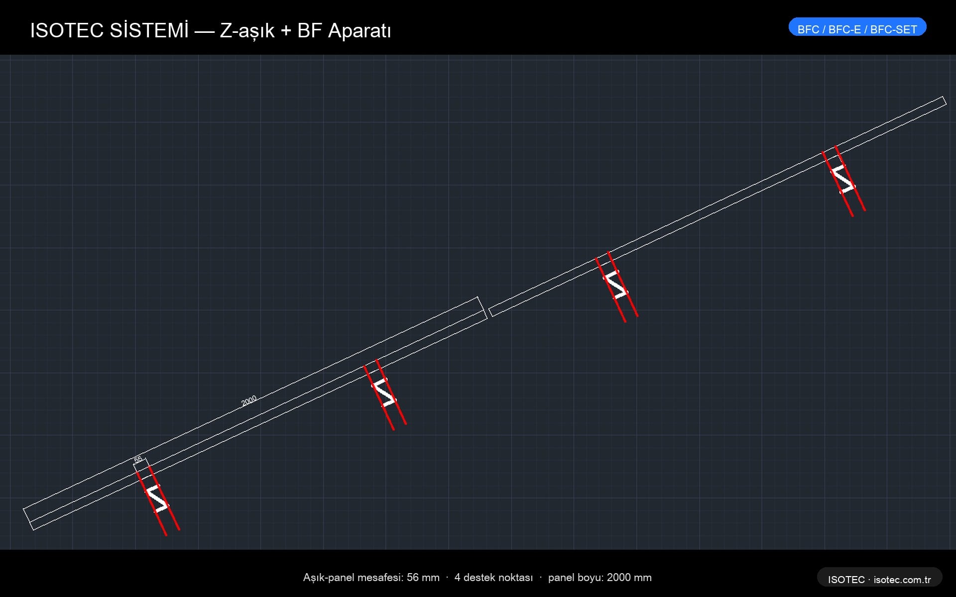
The beams are vertical (perpendicular to the ground, short). The Z-profile purlins extend horizontally. A BF 56 mm spacer is inserted between the purlin and the panel.
- ✓ Low steel content, quick assembly, economical.
- ✓ Bifacial performance with BF apparatus and Inclined-C equal
- ✓ Standard column, easy supply.
- ✓ Slot design compatible with thermal expansion.
CAD comparison — purlin-panel distances
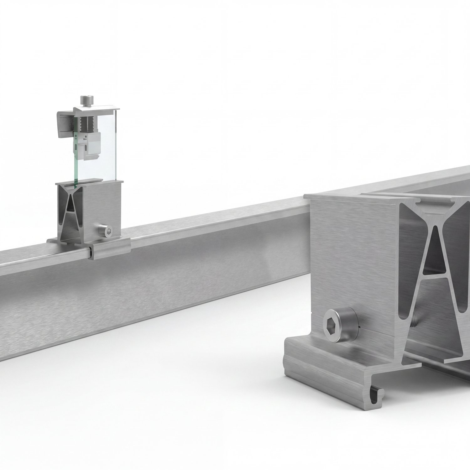
How does the BF adapter work?
The ISOTEC BF adapter is a device placed between the Z-shaped purlin and the bottom surface of the panel. spacer + clamp systemIt maximizes the radiation falling on the back surface of the panel by creating a distance of 56 mm.
Design features
- Spacer body: EN AW-6005A T6 anodized aluminum (3.0 mm wall)
- Distance: The distance between the purlin's top surface and the panel's bottom surface is 56 mm.
- Slot design: Panel thermal expansion accommodated (±2 mm tolerance)
- Screw: Stainless steel A2 M8×40 hexagonal
Clamp variations
| Code | Medicine | Use |
|---|---|---|
| BFC | Glass-to-glass edge | For frameless glass-to-glass panels at panel edges. |
| BFC-E | Medium grip | Center panel, shared grip, frameless. |
| BFC-SET | Complete set | All components are pre-packaged, quick assembly. |
CAD details — ISOTEC system
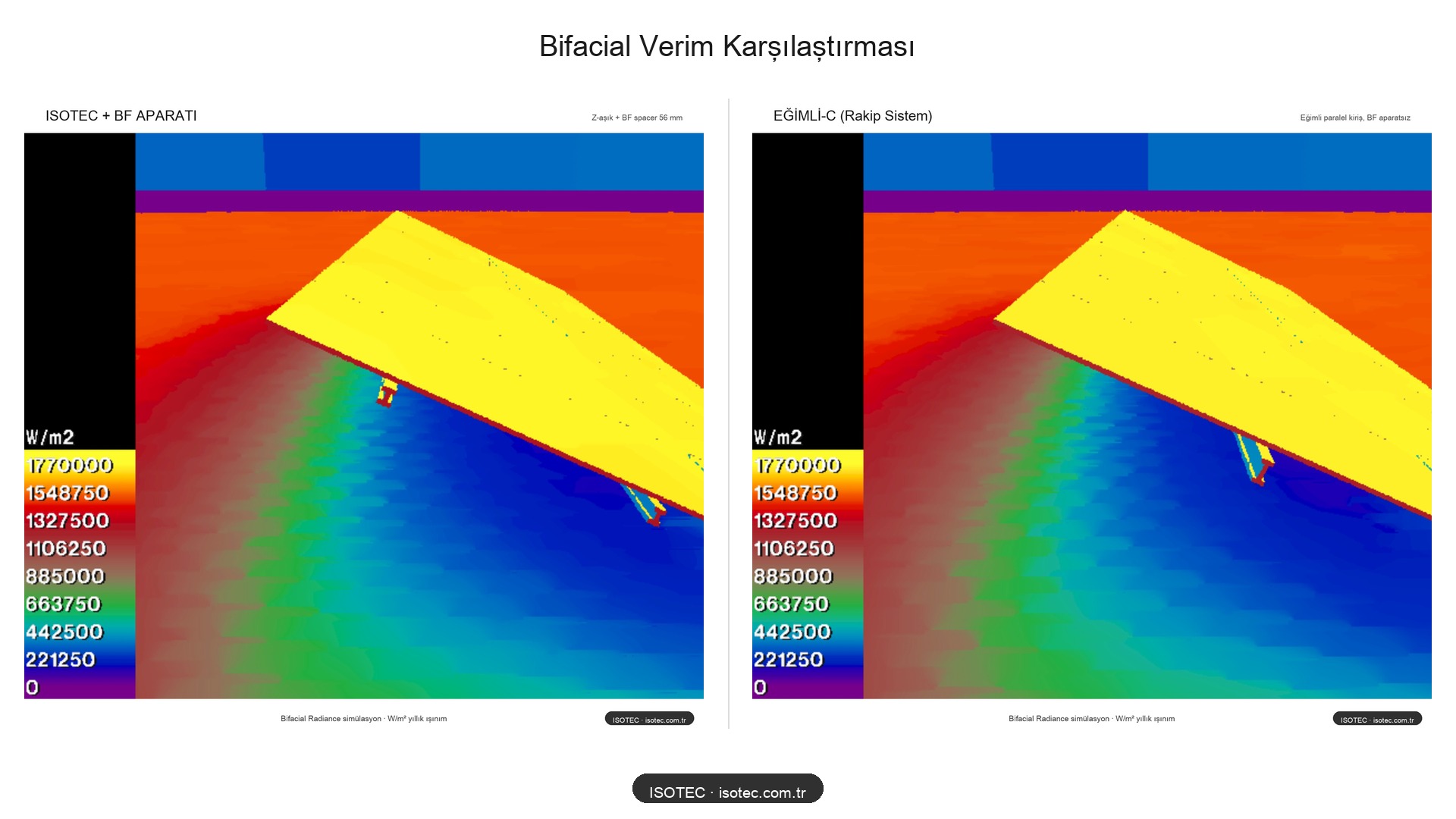
Bifacial Radiance Simulation Results
The results are from NREL's (US National Renewable Energy Laboratory) open-source program. Bifacial Radiance This was achieved using a Python library. A scanner-based radiation calculation is performed that accurately reflects field conditions.
Heat map comparison
Warm (yellow) colors indicate high irradiation (1.77 MWh/m² annually), while cool (blue) colors indicate shaded areas. In both systems, the front surface of the panel (the upper yellow area) receives homogeneous irradiation; the difference is the panel. on the back surface It is seen.
Numerical results
| System | Bifacial Gain | Shadow Line | Cost |
|---|---|---|---|
| Sloping-C (Opponent) | ~%18-20 | 1 big | 💰💰💰 High |
| ISOTEC + BF Adapter | %18 | 2 small | 💰 Economical |
| ISOTEC (without BF adapter) | ~%10-12 | 2 nearby shadows | 💰 Lowest |
The same bifacial production, shorter beam, less steel, faster assembly. The cost difference is significant at the field scale.